Eureka AIR delivers breakthrough ideas for toughest innovation challenges, trusted by R&D personnel around the world.

High-voltage cascaded isolation transformer with solid insulation structure

A technology of isolation transformers and high-voltage cascading, applied in transformer/inductor components, transformer/inductor coils/windings/connections, preventing/reducing unwanted electric/magnetic effects, etc. Source equipment isolation transformer, difficult to meet application requirements, and difficult operation and maintenance, etc., to achieve the effect of excellent fire and explosion protection performance, compact structure, and high insulation strength

Pending Publication Date: 2020-04-17
GLOBAL ENERGY INTERCONNECTION RES INST CO LTD +2
View PDF0 Cites 0 Cited by
  • Summary
  • Abstract
  • Description
  • Claims
  • Application Information

AI Technical Summary

Problems solved by technology

Commonly used transformers above 35kV in the power field, in order to achieve voltage isolation and provide necessary main insulation, basically use oil-immersed transformers, which have fire risks, so they cannot be used as isolation transformers for DC passive equipment
For transformers of 35kV and below, although there is a solid insulation structure design, this solid insulation material generally uses epoxy resin, which has problems of large partial discharge and serious space charge accumulation under DC voltage, and the voltage level is too low to meet the application requirements.
There is also a gas-filled transformer, although it is an oil-free design, but because the gas pressure reaches above 0.5MPa in order to ensure insulation, there is a risk of gas leakage during operation, making operation and maintenance difficult

Method used


Image

  • High-voltage cascaded isolation transformer with solid insulation structure
  • High-voltage cascaded isolation transformer with solid insulation structure
  • High-voltage cascaded isolation transformer with solid insulation structure

Examples


Embodiment Construction

[0035] The technical solutions of the present invention will be clearly and completely described below in conjunction with the accompanying drawings. Apparently, the described embodiments are some of the embodiments of the present invention, but not all of them. Based on the embodiments of the present invention, all other embodiments obtained by persons of ordinary skill in the art without making creative efforts belong to the protection scope of the present invention.

[0036] In the description of the present invention, it should be noted that the terms "center", "upper", "lower", "left", "right", "vertical", "horizontal", "inner", "outer" etc. The indicated orientation or positional relationship is based on the orientation or positional relationship shown in the drawings, and is only for the convenience of describing the present invention and simplifying the description, rather than indicating or implying that the referred device or element must have a specific orientation, ...


PUM


Abstract

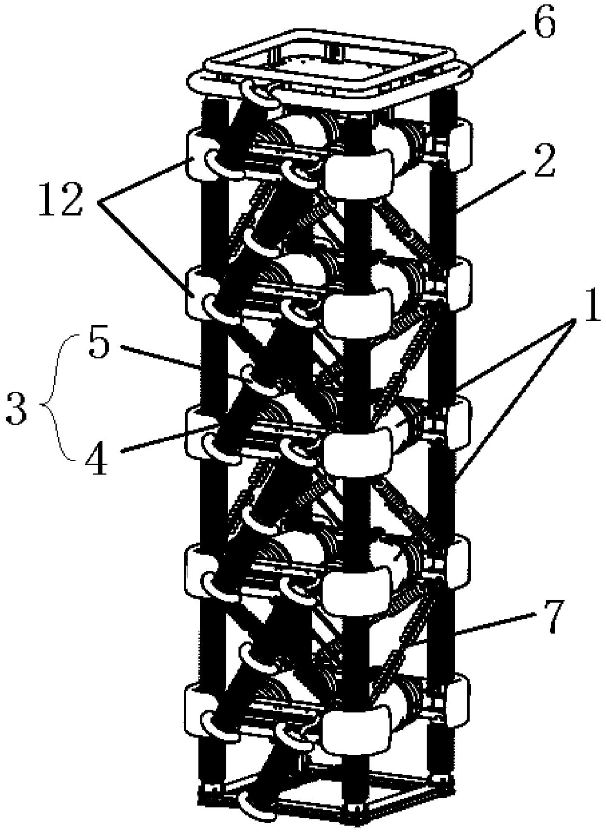
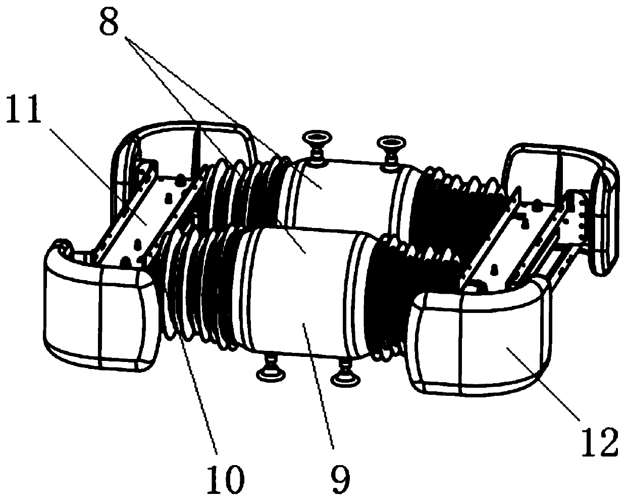
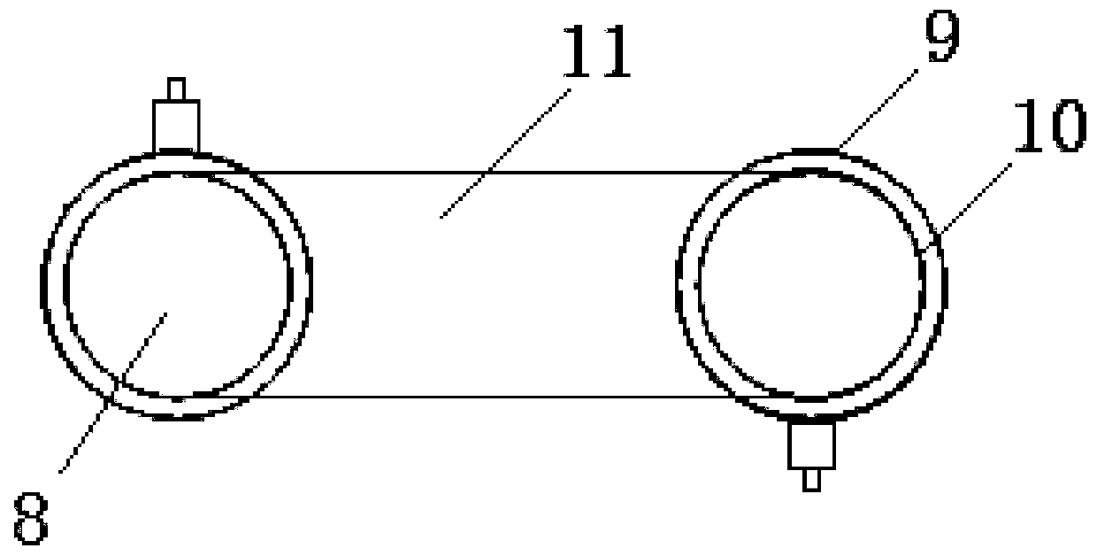
The invention provides a high-voltage cascaded isolation transformer with a solid insulation structure, and belongs to the technical field of isolation transformers. The high-voltage cascaded isolation transformer comprises at least one transformer module, the transformer module is provided with two cascaded sub-transformer units which are arranged in parallel, and each sub-transformer unit comprises: a high-voltage winding which is of a solid insulation structure; and a low-voltage winding, wherein the low-voltage winding and the high-voltage winding are coaxially arranged, and the low-voltage windings of the two sub-transformer units are connected in series. The high-voltage cascade isolation transformer with the solid insulation structure adopts an insulation material suitable for direct-current voltage, semiconductor shielding and main insulation staged pouring technologies are adopted, low partial discharge design and high insulation tolerance of the transformer can be achieved, acascade connection mode is adopted, a unit modular structure is formed, and application can be expanded according to different voltage classes. Power supply from the ground potential to tens of kilovolts or even hundreds of kilovolts or above can be achieved, and high-potential ground isolation is achieved.

Description

technical field [0001] The invention relates to the technical field of isolation transformers, in particular to a high-voltage cascaded isolation transformer with a solid insulation structure. Background technique [0002] High-voltage isolation transformer refers to the isolation of the respective currents between the coils of the primary side (primary side) and the secondary side (secondary side) through certain insulation measures, so that the input winding and the output winding are electrically separated. transformer. [0003] With the development of DC transmission design, some new equipments have appeared in the DC system, such as DC circuit breakers, etc. These equipments are passive equipments and need external energy supply; It is also impossible to obtain energy in the DC system, so external energy supply is required. This external energy supply equipment needs to have several characteristics: (1) It can realize the transmission of electric energy from ground pot...

Claims


Application Information

Patent Timeline
IPC IPC(8): H01F27/30H01F27/32H01F27/34H01F27/36
CPCH01F27/30H01F27/324H01F27/327H01F27/34H01F27/36
Inventor 张升刘远詹婷魏晓光高冲贺之渊庞辉王成昊周万迪
Owner GLOBAL ENERGY INTERCONNECTION RES INST CO LTD
Why Eureka
Eureka Blog
Learn More