A flyback converter and its control method

A technology of flyback converter and control method, applied in control/regulation system, conversion of DC power input to DC power output, instruments, etc., can solve the problem of large oscillation of flyback circuit, reduce the loss of switching tube and optimize EMI , the effect of improving efficiency

Active Publication Date: 2021-02-23
MORNSUN GUANGZHOU SCI & TECH
View PDF6 Cites 0 Cited by
  • Summary
  • Abstract
  • Description
  • Claims
  • Application Information

AI Technical Summary

Problems solved by technology

[0004] The technical problem to be solved by the present invention is to provide a flyback converter and its control method to solve the problem of large oscillation in the existing active clamp flyback circuit

Method used


Image

  • A flyback converter and its control method
  • A flyback converter and its control method
  • A flyback converter and its control method

Examples


Embodiment 1

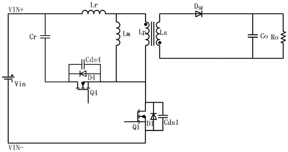
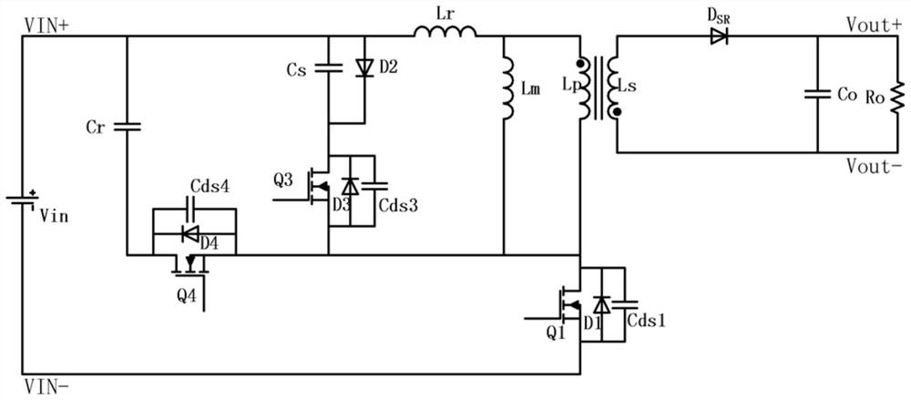
[0046] like figure 2 As shown, the present invention discloses a flyback converter, including a main power circuit, a clamping circuit and an output filter circuit; the main power circuit is provided with a transformer and a main switching tube Q1, and the clamping circuit is provided with a clamp Bit capacitor Cr and main clamping tube Q4, the first end of the primary winding Lp of the transformer is used as the positive input terminal VIN+ of the flyback converter, the second end of the primary winding Lp, the main switch The drain of the transistor Q1 is connected to the source of the main clamping transistor Q4, the drain of the main clamping transistor Q4 is connected to the positive input terminal VIN+ through the clamping capacitor Cr, and the main switching transistor Q1 The source of the flyback converter is used as the negative input terminal VIN- of the flyback converter; the secondary winding Ls of the transformer is used to output direct current to the load Ro th...

Embodiment approach

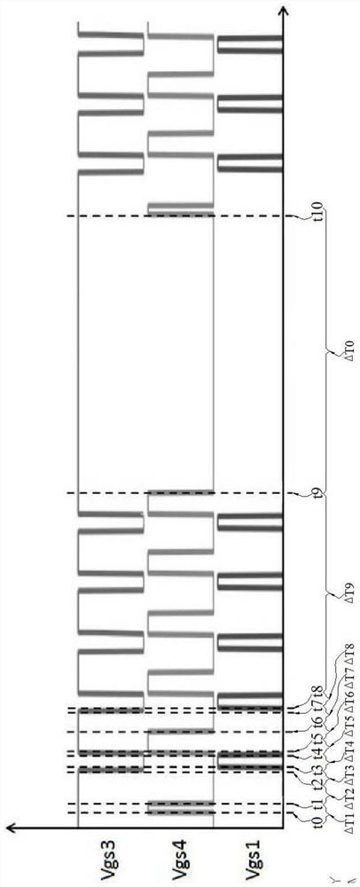
[0093] The ΔT1, ΔT3, ΔT5, ΔT6, and ΔT8 all take the minimum value, that is:

[0094] At the end of the first period, that is, at time t1, the excitation inductance Lm and leakage inductance Lr of the transformer are stored to the minimum energy required to realize the zero-voltage switching of the main switching tube Q1;

[0095] At the end of the third period, that is, at time t3, the voltage of the parasitic capacitance Cds1 of the main switching transistor Q1 drops to zero;

[0096] At the end of the fifth period, that is, at time t5, the drain-source voltage of the main switching transistor Q1 rises to Vin+Vc;

[0097] At the end of the sixth period, that is, at time t6, the secondary current of the transformer is reduced to zero;

[0098] At the end of the eighth period, that is, at time t8, the voltage of the parasitic capacitor Cds1 of the main switching transistor Q1 drops to zero.

[0099] It should be noted that the values ​​of ΔT1 , ΔT3 , ΔT5 , and ΔT6 can also be...

Embodiment 3

[0101] On the basis of the above-mentioned embodiment 1 or embodiment 2, this embodiment 3 also adopts the following preferred implementation modes:

[0102] The sum of the working time and the non-working time is a constant value T', and its value is set according to the design requirements of the flyback converter.

[0103] Preferably: the value of the number N of cycle periods in the working time increases with the increase of the load Ro, and ΔT0=T'-(ΔT3+ΔT4+ΔT5+ΔT6).

[0104] Therefore, when the load Ro is lighter, the duration of the working time is shorter, and the duration ΔT0 of the non-working time is longer, on the contrary, when the load Ro is heavier, the duration of the working time is longer, The shorter the duration ΔT0 of the non-working time, the equivalent operating frequency of the flyback converter changes in the same direction as the load Ro. Therefore, the switching tube loss of the flyback converter of the present invention can be reduced and the light-...


PUM


Abstract

The invention discloses a flyback converter and a control method thereof. By adding a clamping diode, an auxiliary capacitor and an auxiliary clamping tube in the clamping circuit, and using the main switch drive signal, the main clamp drive signal and the auxiliary clamp drive The signals are driven separately, so that the flyback converter works intermittently according to the alternating cycle of working time and non-working time. During the working time, the three switching tubes are in the intermittent working mode, and all can realize zero-voltage switching; and, in the working time In the sixth period of time, the leakage inductance energy of the transformer can be recovered to improve the efficiency of the flyback converter; moreover, the clamp diode can be used to clamp the transformer, so that the second and seventh periods of the working time and the non-working time Eliminate oscillation; therefore, the present invention improves the efficiency of the flyback converter and reduces the frequency of the flyback converter on the premise that each switching tube in the flyback converter can realize zero-voltage switching during the whole working process. Oscillation during work, optimized for EMI.

Description

technical field [0001] The invention relates to the field of switching converters, in particular to a flyback converter and a control method for the flyback converter. Background technique [0002] With the rapid development of power electronics technology, switching converters are used more and more widely, especially people put forward more requirements for switching converters with high power density, high reliability and small size. The flyback topology has the advantages of simple structure and low price, and is widely used in low-power switching converters. However, the common flyback topology is a hard switch and cannot recover leakage inductance energy, thus limiting the efficiency and size of the common flyback topology. In order to seek a breakthrough in the size and efficiency of low-power switching converters, soft switching technology has become a research hotspot in power electronics technology. [0003] At present, the representative of the flyback topology ...

Claims


Application Information

Patent Timeline
Patent Type & Authority Patents(China)
IPC IPC(8): H02M3/335H02M1/44
CPCH02M1/44H02M3/33569H02M1/0058Y02B70/10
Inventor 尹向阳钟天明马守栋王志燊
Owner MORNSUN GUANGZHOU SCI & TECH
Why Eureka
Try Eureka