Air conditioning unit
A technology of air-conditioning unit and air-conditioning shell, which is applied in air handling equipment, heating/cooling equipment, vehicle maintenance, etc., and can solve problems such as large temperature deviation of blown air
- Summary
- Abstract
- Description
- Claims
- Application Information
AI Technical Summary
Problems solved by technology
Method used
Image
Examples
no. 1 approach
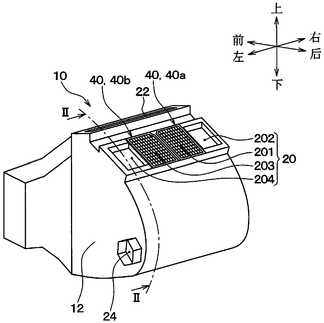
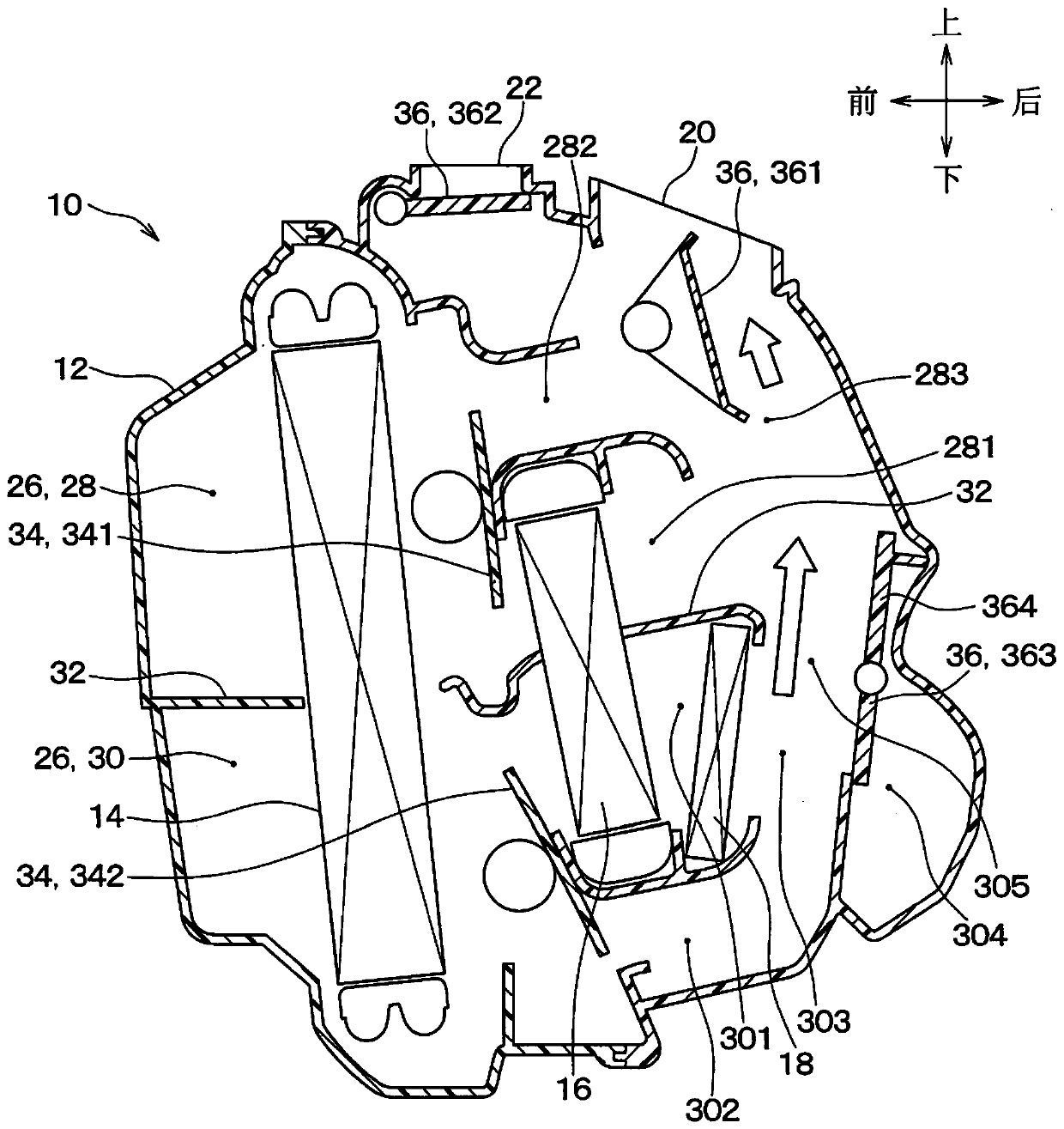
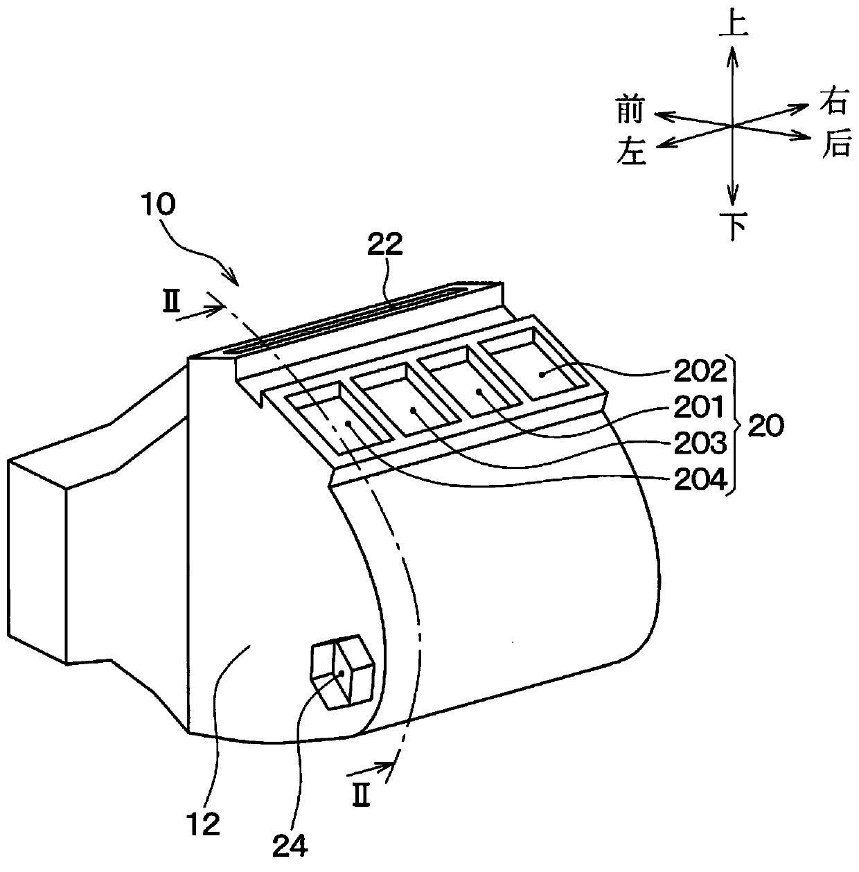
[0044] first of all, yes figure 1 , 2 The schematic structure of the whole air-conditioning unit 10 of this embodiment shown is demonstrated. The air conditioning unit 10 is a vehicle air conditioning unit constituting a part of the vehicle air conditioner. This air conditioning unit 10 is mounted on the front side of the vehicle rather than the front seats in the vehicle interior. More specifically, this air conditioning unit 10 is arranged inside the instrument panel. The air conditioning unit 10 blows the air that has passed through the heat exchanger toward the vehicle interior.
[0045] The air conditioning unit 10 includes an air conditioning case 12 , a blower (not shown), an evaporator 14 , a heater core 16 , and a PTC heater 18 .
[0046] The air conditioning case 12 constitutes an outer casing of the air conditioning unit 10 . like figure 1 As shown, a plurality of blowing openings 20 , 22 , 24 are formed in the air conditioner case 12 . The plurality of blowi...
no. 2 approach
[0074] like Figure 7 As shown, the present embodiment differs from the first embodiment in that the adjustment member 40 has the baffle 48 . Other configurations of the air conditioning unit 10 are the same as those of the first embodiment.
[0075] The two adjustment members 40 respectively have a frame 42 , a grid 44 and two baffles 48 . The baffle 48 is a plate member that blocks air flow.
[0076] The grid 44 and the two baffles 48 are arranged in an area surrounded by the frame 42 . The two baffles 48 are arranged in a part of the peripheral portion of the central portion in the area surrounded by the frame 42 . Therefore, the baffle 48 is arranged offset in the area surrounded by the frame 42 . The grid 44 is arranged in the area surrounded by the frame 42 except for the two baffles 48 . The frame 42, the grid 44, and the two baffles 48 are constituted by an integral molding made of resin. These may also not be made of resin.
[0077] The lattice area 47 where th...
no. 3 approach
[0095] Such as Figure 9 As shown, in the present embodiment, a plurality of openings 48a are formed in the two shutters 48 for each of the two adjustment members 40 . Other configurations of the air conditioning unit 10 are the same as those of the first embodiment.
[0096] In this way, a plurality of openings 48 a may be formed in the baffle 48 . There may be one opening 48a. By forming one or more openings 48 a in the baffle 48 , resistance to air flow in the baffle region 49 can be reduced. Accordingly, it is possible to adjust the resistance to the airflow of the blowing opening provided with the adjustment member 40 .
PUM
 Abstract
Description
Claims
Application Information
 - R&D Engineer
- R&D Manager
- IP Professional
- Industry Leading Data Capabilities
- Powerful AI technology
- Patent DNA Extraction
Browse by: Latest US Patents, China's latest patents, Technical Efficacy Thesaurus, Application Domain, Technology Topic, Popular Technical Reports.
© 2024 PatSnap. All rights reserved.Legal|Privacy policy|Modern Slavery Act Transparency Statement|Sitemap|About US| Contact US: help@patsnap.com


