
Electric pump system and method

A technology for mechanical pumps and pump inlets, applied in the field of fluid temperature assessment, which can solve the problems of oil pumps not monitoring oil conditions, large physical space, and inability to accurately determine the temperature

Active Publication Date: 2020-04-17
TESLA INC
View PDF13 Cites 4 Cited by
  • Summary
  • Abstract
  • Description
  • Claims
  • Application Information

AI Technical Summary

Problems solved by technology

Traditional oil pumps do not monitor oil condition and therefore require periodic oil changes as the condition of the oil, pump and motor cannot be independently verified
Another side effect is that conventional oil pumps are not (cannot) be designed to accurately determine temperature, partly because any temperature sensors are located outside the conventional pump system or in the area that represents the oil flowing through the pump
Furthermore, conventional oil pumps are often large and unwieldy due to the attachment mechanism of the different components and require a large physical space for the pump

Method used


Image

  • Electric pump system and method
  • Electric pump system and method
  • Electric pump system and method

Examples


Embodiment Construction

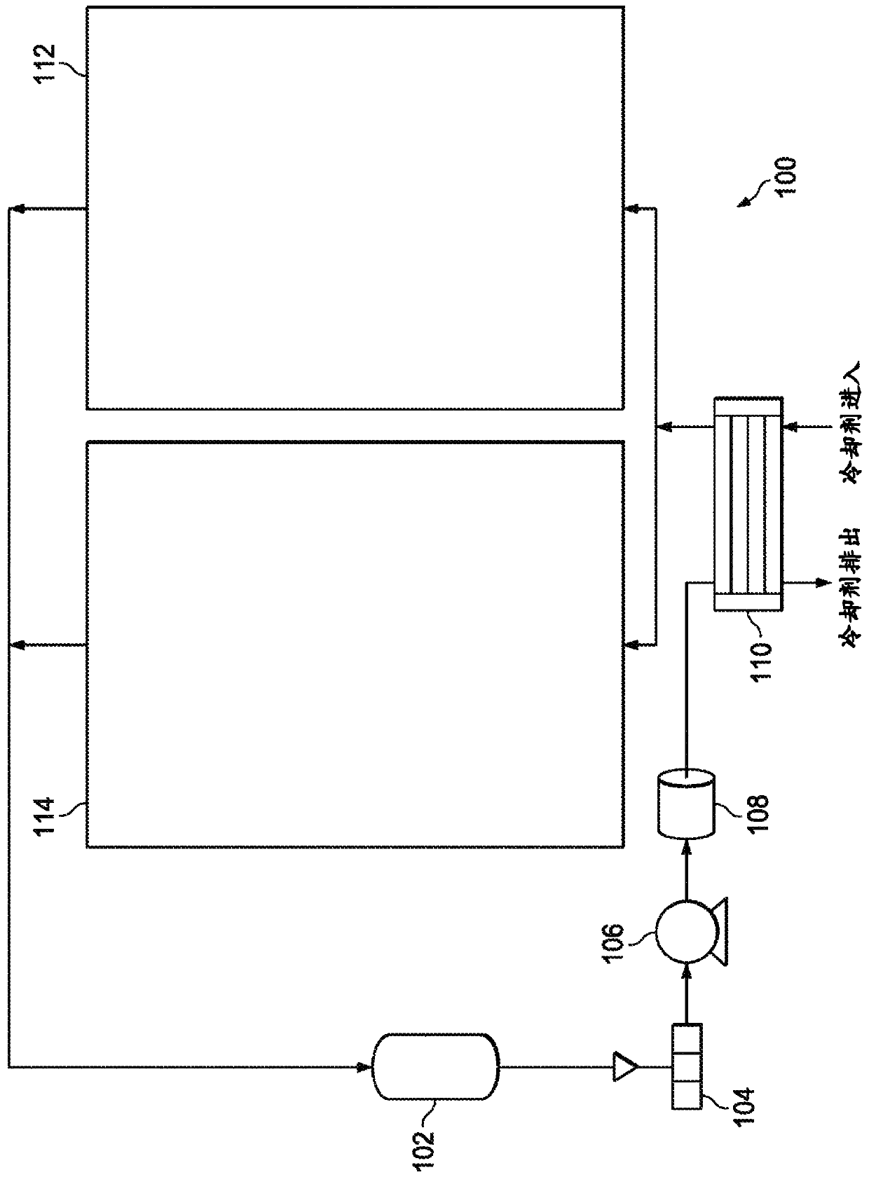
[0030] figure 1 A schematic diagram of a cooling and lubrication system 100 for circulating a fluid (eg, oil) through various components of an electric drive unit of an electric vehicle is shown in accordance with disclosed embodiments. Subsequent descriptions of other figures refer to figure 1 s component. exist figure 1 In , general reference numerals may be used to refer to components identified in those figures. Additionally, although the embodiments described herein are in the context of oil-based systems, other fluids may be used. For example, any fluid that provides suitable lubrication, heat transfer, and flow characteristics for a particular application or pump size can be used.

[0031] From an oil reservoir 102 (an oil reservoir external to the drive unit), which may include an oil sump or dry sump system, the oil flows through a mesh filter 104 to an electric pump system 106 . Oil pumped from the electric pump system 106 passes through an oil filter 108 and...


PUM


Abstract

An electric pump system and method of operating the same involves pumping a fluid through a fluid passageway defined in a mechanical pump from a pump inlet to a hollow shaft of a motor, through the hollow shaft to an internal motor cavity defined by a housing of the motor, and through another fluid passageway defined in the motor housing and mechanical pump that leads to a pump outlet. The systemand method further involve pumping the fluid through another fluid passageway defined in the mechanical pump from yet another pump inlet to the pump outlet. The temperature of fluid exiting the hollowshaft can be assessed and used by an electronic control unit (ECU) of the electric pump system to control the same. The electric pump system can be part of a cooling and lubrication system for an electric vehicle transmission, gearbox, differential or transfer case, for example.

Description

[0001] Cross References to Related Applications [0002] This PCT application claims priority to U.S. Patent Application No. 15 / 944,841, filed April 4, 2018, entitled "ELECTRIC PUMP SYSTEM ANDMETHOD," and claims priority to U.S. Patent Application No. 15 / 944,841, filed June 30, 2017, entitled "ELECTRIC PUMP SYSTEM ANDMETHOD" PUMP SYSTEM AND TECHNIQUES" Provisional Application No. 62 / 527,699 priority. U.S. Patent Application No. 15 / 944,841, filed April 4, 2018, entitled "ELECTRIC PUMP SYSTEM AND METHOD," claims U.S. Provisional Application No. filed June 30, 2017 under 35 U.S.C. §119(e) Priority No. 62 / 527,699, both of which are hereby incorporated by reference in their entirety for all purposes, and made a part of this PCT application. [0003] This PCT application is related to U.S. Patent Application No. 15 / 637,313, filed June 29, 2017, entitled "SYSTEM AND METHOD FORMONITORING STRESS CYCLES," which is incorporated herein by reference in its entirety. technical field [0...

Claims


Application Information

Patent Timeline
Patent Type & Authority Applications(China)
IPC IPC(8): F04B1/04F04B17/03F04B49/06F04B51/00F04B53/08F04B53/16F04B53/18F04C11/00F04C14/28F04C15/00F04C2/10H02K11/33H02K7/14H02K9/19
CPCF04C2/102F04C11/008H02K1/32H02K7/14H02K9/19H02K11/33F04C2240/603F04C2240/808F04C14/28F04C15/0096F04B1/04F04B17/03F04B49/065F04B51/00F04B53/08F04B53/16F04B53/18F04B2201/1201F04B2205/11F04C2/104Y02T10/64H02K11/25F04C2/10F04C14/26F04C15/008F04C15/06F04C2240/40F05B2260/201F05B2240/61F04C29/02
Inventor S·M·格雷夫斯E·贝勒马尔朱宇飞B·德拉尔D·A·西尔瓦·罗德里格兹
Owner TESLA INC
Learn More