
A machine automatic detection device for straight pins

An automatic detection and cylindrical pin technology, applied in sorting and other directions, can solve the problems of reducing detection efficiency, many mechanical movements, and poor feeding, and achieve the effect of high detection efficiency, improved accuracy, and avoidance of low efficiency and errors.

Inactive Publication Date: 2020-08-18
SHANDONG INST FOR PROD QUALITY INSPECTION
View PDF8 Cites 0 Cited by
  • Summary
  • Abstract
  • Description
  • Claims
  • Application Information

AI Technical Summary

Problems solved by technology

[0007] Although the above-mentioned prior art has improved production efficiency compared with manual detection, the feeding mechanism of the above-mentioned device uses a funnel placed above the equipment, and the material is unloaded by the gravity of the cylindrical pin itself. There are several problems in this unloading method. First of all, if there are a large number of straight pins in the funnel, it is easy to cause blockage, and the feeding is not smooth. Although there is a vibrator, if the vibrator is used to vibrate when the block is blocked, the straight pins will only be blocked at the feeding port, which is very inconvenient. , and the material is slowly unloaded by the gravity of the cylindrical pin itself, the efficiency is not high. Although the length sensor can effectively measure the length of the cylindrical pin, it needs the length sensor to clamp both ends of the cylindrical pin for measurement. After the measurement is completed, the cylindrical pin needs to be returned for measurement. There are too many mechanical actions in the process, which wastes time and further reduces the detection efficiency

Method used


Image

  • A machine automatic detection device for straight pins
  • A machine automatic detection device for straight pins
  • A machine automatic detection device for straight pins

Examples


Embodiment 1

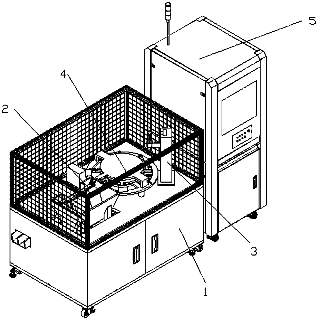
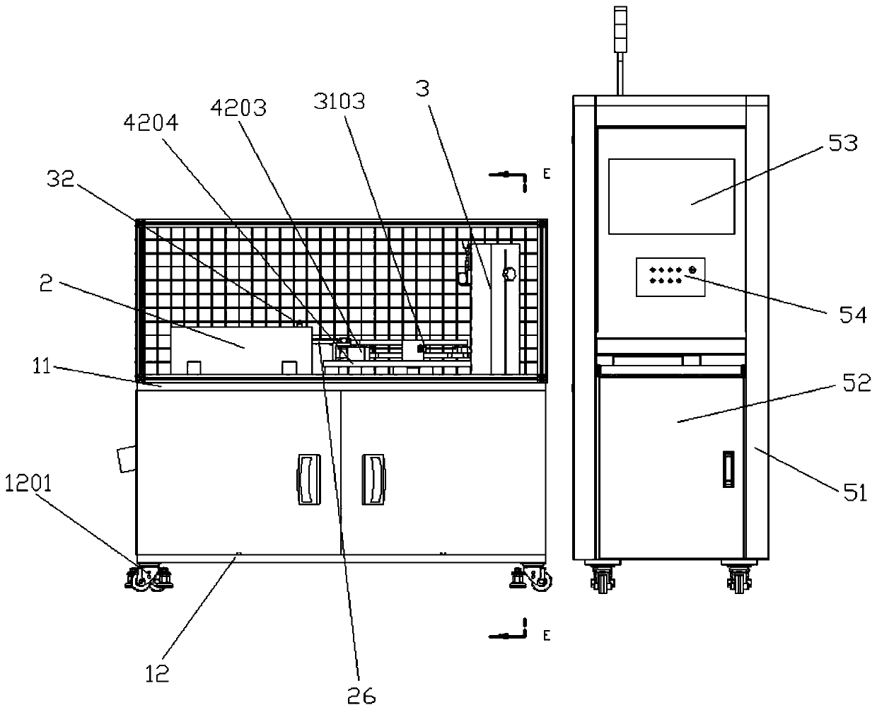
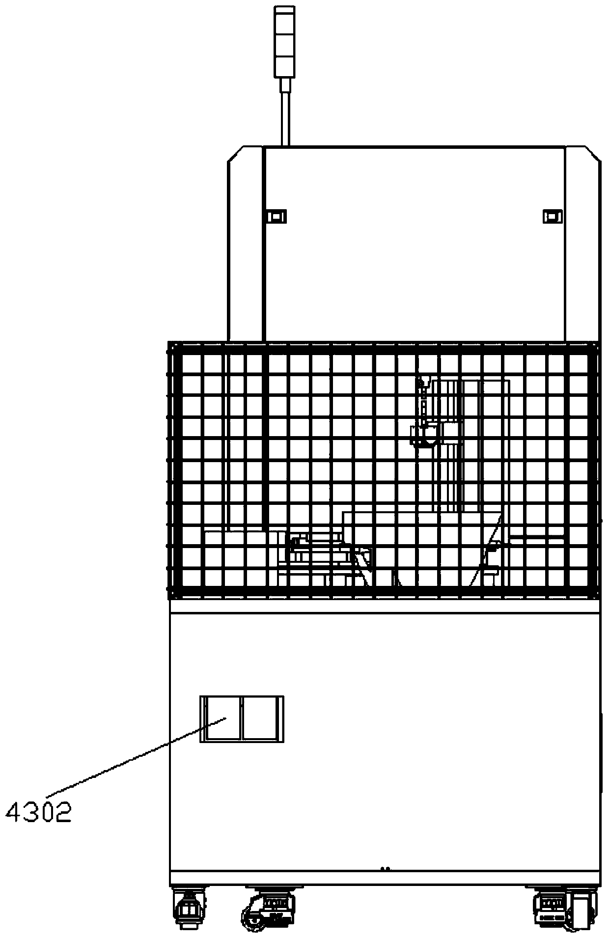
[0039] An automatic detection device for cylindrical pins, comprising a frame 1, a feeding device 2, a detection device 3, a feeding device 4, and a control device 5, the frame 1 includes a top plate 11 and a bottom plate 12, and the bottom of the bottom plate 12 is provided with There are universal wheels 1201 to facilitate movement, the feeding device 2 is arranged on the bottom plate 12 and passes through the top plate 11, the feeding device 4 includes a driving device 41, a rotary device 42, and a feeding device 43. The driving device 41 is arranged on the bottom plate 12, the turning device 42 is arranged on the top plate 11, the unloading device 43 is arranged on the top plate 11, and the driving device 41 communicates with the The rotary device 42 is connected, the unloading device 43 is arranged on one side of the rotary device 42, the detection device 3 is arranged on the top plate 11 and is located on the side of the rotary device 42, and the feeding device 2 passes t...


PUM


Abstract

The invention discloses an automatic detection device for a cylindrical pin machine, and relates to the field of mechanical detection. The automatic detection device comprises a rack, a loading device, a detection device, a feeding device and a control device. The automatic detection device is characterized in that the rack comprises a top plate and a bottom plate; the loading device is arranged on the bottom plate and penetrates through the top plate; the feeding device comprises a driving device, a rotating device and a discharging device. The driving device is arranged on the bottom plate;the rotating device is arranged on the top plate; the discharging device is arranged on the top plate; the driving device is connected with the rotating device through a stepping assembly. The discharging device is arranged on one side of the rotating device. The detection device is arranged on the top plate and located on one side of the rotating device. The loading device is connected with the rotating device through a positioning piece. The length and the diameter of the cylindrical pin can be rapidly detected and the detection efficiency is improved.

Description

technical field [0001] The invention relates to the field of mechanical detection, in particular to an automatic detection device for cylindrical pin machines. Background technique [0002] Pins are generally used to connect, lock parts or for assembly positioning, and can also be used as parts of safety devices. In the mechanical field, pins are mainly used for assembly positioning, and can also be used as overload shear connections in connection and relaxation level safety devices. The cylindrical pin is fixed in the pin hole with a slight interference. [0003] The type of pin is selected according to its working requirements in use. The diameter of the pin used for connection can be determined empirically according to the structural characteristics of the connection, and the strength check should be done if necessary. The diameter of the positioning pin can be determined according to the structure. The length of the pin in each connector is about 1-2 times its diamet...

Claims


Application Information

Patent Timeline
Patent Type & Authority Patents(China)
IPC IPC(8): B07C5/10B07C5/02B07C5/36
CPCB07C5/02B07C5/10B07C5/365
Inventor 陈威李林林李丽王健康
Owner SHANDONG INST FOR PROD QUALITY INSPECTION
Learn More