A gold leaf processing knocking device

A gold leaf and gear technology, which is applied in the field of gold leaf processing and knocking devices, can solve the problems of workers being injured by injuries, large manpower, and time-consuming, and achieve the effect of avoiding injuries

Active Publication Date: 2021-06-22
义乌市丹航科技有限公司
View PDF14 Cites 0 Cited by
  • Summary
  • Abstract
  • Description
  • Claims
  • Application Information

AI Technical Summary

Problems solved by technology

[0004] In order to overcome the need to frequently flip the patch intermittently during the manual processing of gold leaves, it takes a lot of time for the workers to swing the hammer up and down with their hands, and it also consumes a lot of manpower. The shortcoming of easily injuring the worker when holding the gold leaf by hand, the technical problem of the present invention is to provide a gold leaf processing and knocking machine that can clamp the gold leaf and smash it, and can intermittently knock both sides of the gold leaf. hit device

Method used


Image

  • A gold leaf processing knocking device
  • A gold leaf processing knocking device
  • A gold leaf processing knocking device

Examples


Embodiment 1

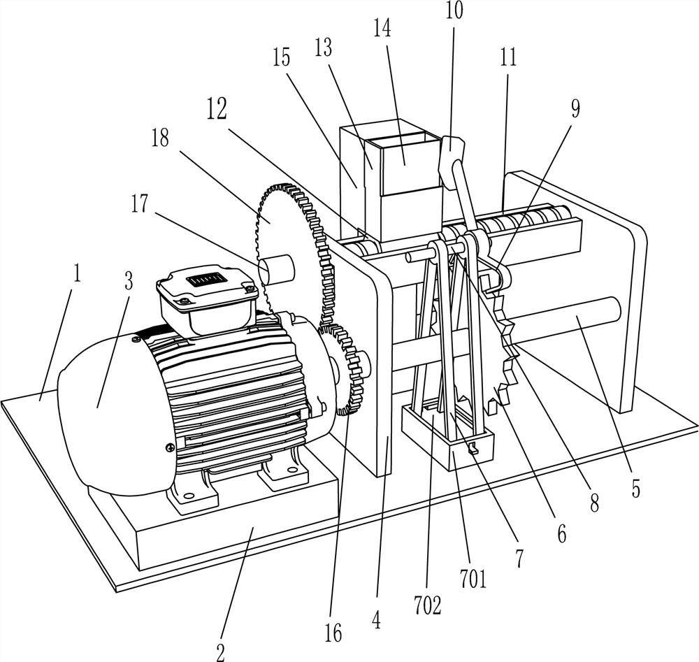
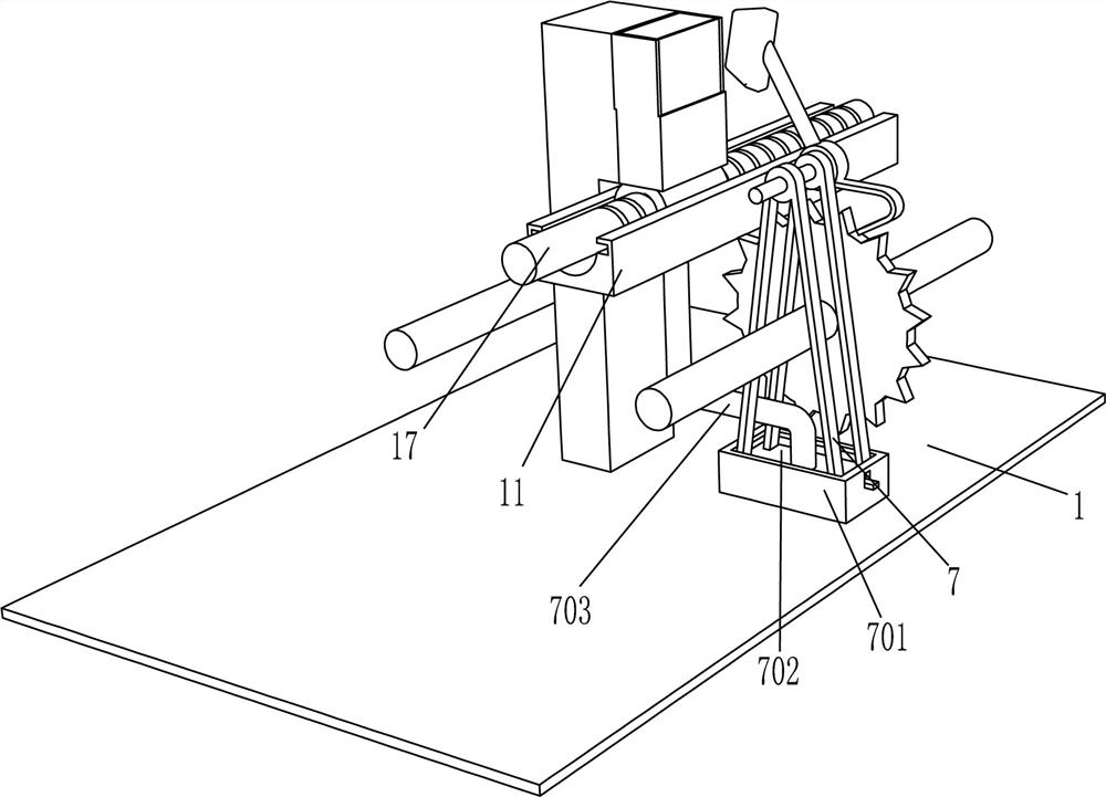
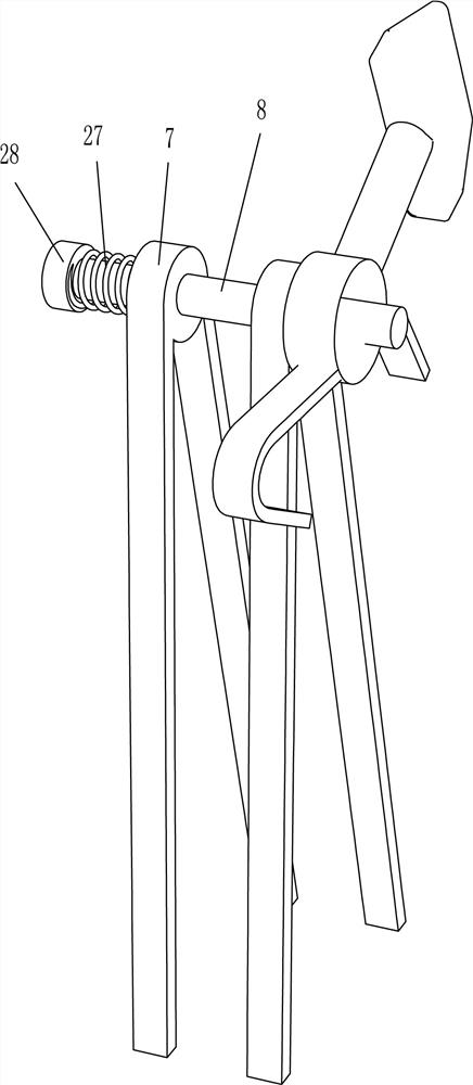
[0019] A gold leaf processing knocking device, such as Figure 1-2 with Figure 4 As shown, it includes a base plate 1 and a backing plate 2, the upper side of the left part of the bottom plate 1 is fixedly connected with the backing plate 2, and also includes a rotating motor 3, a support plate 4, a first rotating shaft 5, a first gear 6, and a first support frame. 7. Fixing mechanism, first fixed shaft 8, first driven bar 9, first hammer body 10, slide rail 11, slider nut 12, fixed frame 13, iron sheet 14 and first stopper 15, backing plate 2 A rotating motor 3 is installed on the upper side, and two support plates 4 are fixedly connected to the upper side of the right part of the bottom plate 1, and a first rotating shaft 5 is rotationally connected between the two supporting plates 4, and the left end of the first rotating shaft 5 is fixedly connected to the output of the rotating motor 3 On the shaft, the middle part of the first rotating shaft 5 is provided with a first...

Embodiment 2

[0024] On the basis of Example 1, such as figure 1 As shown, it also includes a second gear 16, a reciprocating screw 17 and a third gear 18, the left end of the first rotating shaft 5 is fixedly connected with the second gear 16, the slide rail 11 is provided with a reciprocating screw 17, and the reciprocating screw 17 runs through the support plate 4 , the reciprocating screw 17 is rotationally connected with the support plate 4, the reciprocating screw 17 cooperates with the slider nut 12, the left part of the reciprocating screw 17 is provided with a third gear 18, and the third gear 18 meshes with the second gear 16.

[0025] When the first rotating shaft 5 rotates, it drives the second gear 16 to rotate, the second gear 16 drives the third gear 18 to rotate, the third gear 18 drives the reciprocating screw 17 to rotate, and the reciprocating screw 17 drives the slider nut 12 to move repeatedly left and right, thereby realizing fixing Frame 13 automatic left and right re...

Embodiment 3

[0027] On the basis of Example 2, such as image 3 with Figure 5As shown, it also includes a second rotating shaft 19, a fourth gear 20, a fifth gear 21, a second support frame 22, a second fixed shaft 23, a second driven bar 24, a second hammer body 25 and a second block 26. A second rotating shaft 19 is pierced on the support plate 4, and the second rotating shaft 19 is located behind the slide rail 11. The left part of the second rotating shaft 19 is provided with a fourth gear 20, and the second rotating shaft 19 is provided with a fifth gear 21. , there is another square groove on the bottom of the slide rail 11, another fixing mechanism is fixedly connected to the upper and rear sides of the bottom plate 1, the upper part of the other fixing mechanism is arranged in another square groove, and a second fixing mechanism is fixedly connected to the upper side of the other fixing mechanism. The support frame 22, the second rotating shaft 19 passes through the second suppor...


PUM


Abstract

The invention relates to a knocking device, in particular to a gold leaf processing knocking device. The technical problem of the present invention is how to provide a gold leaf processing and striking device that can clamp and strike the gold leaf, and can intermittently strike both sides of the gold leaf. A gold leaf processing knocking device, including a bottom plate and a backing plate, the backing plate is fixedly connected to the bottom plate, and also includes a rotating motor, a supporting plate, a first rotating shaft, a first gear, a fixing mechanism, etc.; the backing plate A rotating motor is installed, and two support plates are fixedly connected to the bottom plate, and a first rotating shaft is connected in rotation between the two supporting plates, the end of the first rotating shaft is fixedly connected to the rotating motor, and the first rotating shaft is covered A first gear is provided, and a fixing mechanism is fixedly connected to the bottom plate. In the present invention, the gold leaf is placed on the fixed frame, without manually holding the gold leaf, which can effectively avoid the damage caused by manual holding.

Description

technical field [0001] The invention relates to a knocking device, in particular to a gold leaf processing knocking device. Background technique [0002] Gold leaf, also known as foil gold, or gold leaf, my country is one of the first countries in the world to use gold leaf, but now most of the gold leaf is used in people's meals, decorations, cosmetics and other fields, because gold is stable in nature, Permanent discoloration, anti-oxidation, anti-humidity, anti-corrosion, anti-mildew, anti-insect bites, anti-radiation, gold foil made of gold has a wide range of uses. The ancient method of making gold leaves is to purify the gold first, and then beat it through repeated tempering. The gold leaves are pure in color, uniform in thickness, and do not change color for a long time. It is a symbol of wealth and magnificence. Nowadays, people use workers to clamp a proper amount of gold leaf into the iron sheet, and then put it on the block, and then the worker hits the gold leaf...

Claims


Application Information

Patent Timeline
Patent Type & Authority Patents(China)
IPC IPC(8): B21J7/14B21J7/32B21J13/08
CPCB21J7/14B21J7/32B21J13/08
Inventor 钟源
Owner 义乌市丹航科技有限公司
Why Eureka
Try Eureka