
Cutting machine for cutting structural wall pipe

A technology of structural wall pipes and cutting machines, which is applied in metal processing and other directions, can solve the problems of structural wall pipes fixing and poor cutting effect, and achieve the effects of ensuring service life, avoiding consumption, and reasonable design

Active Publication Date: 2020-04-21
ANHUI JIELANTE NEW MATERIAL CO LTD
View PDF9 Cites 11 Cited by
  • Summary
  • Abstract
  • Description
  • Claims
  • Application Information

AI Technical Summary

Problems solved by technology

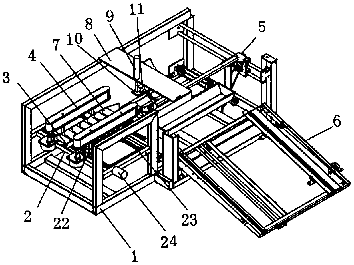
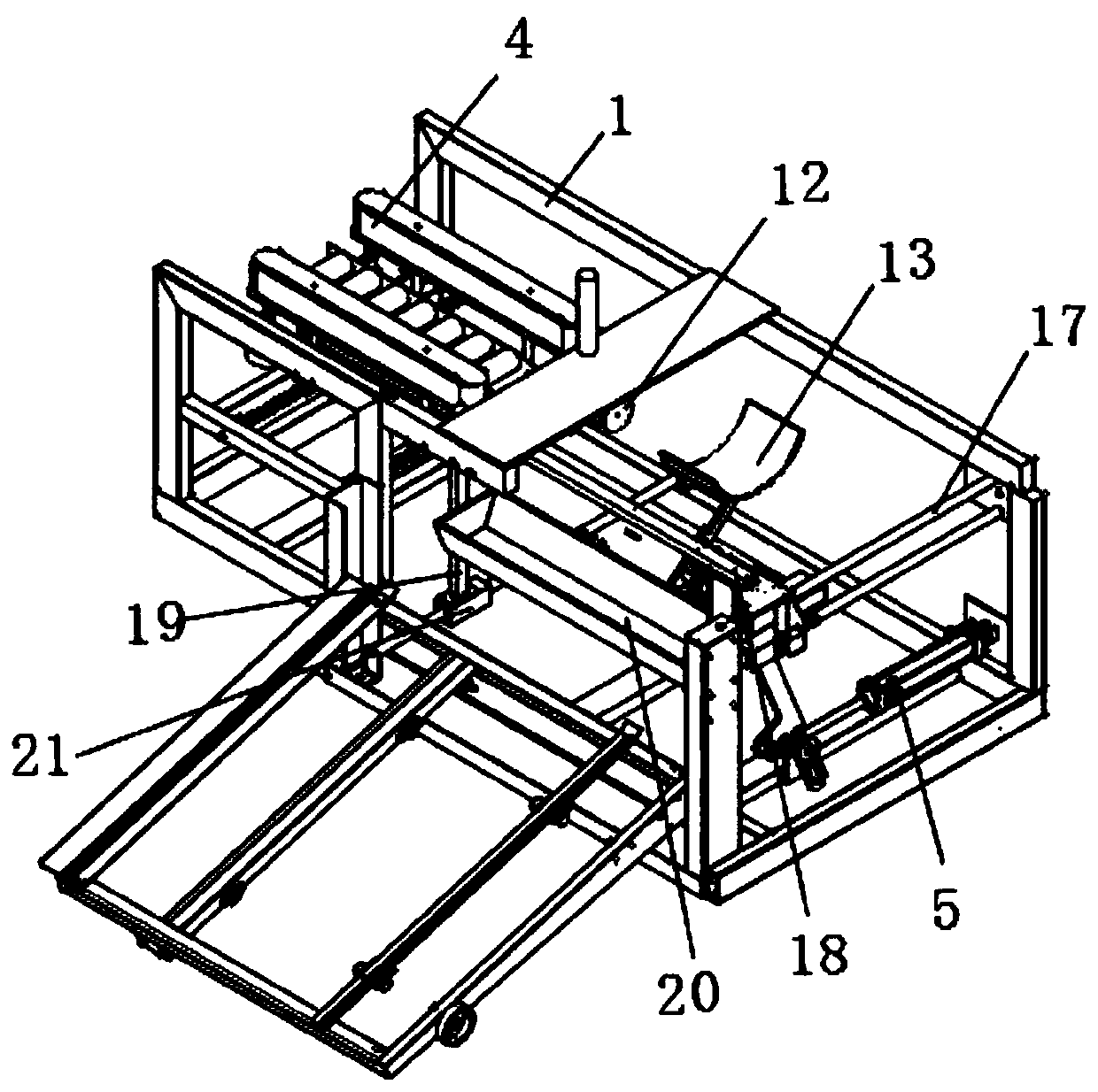
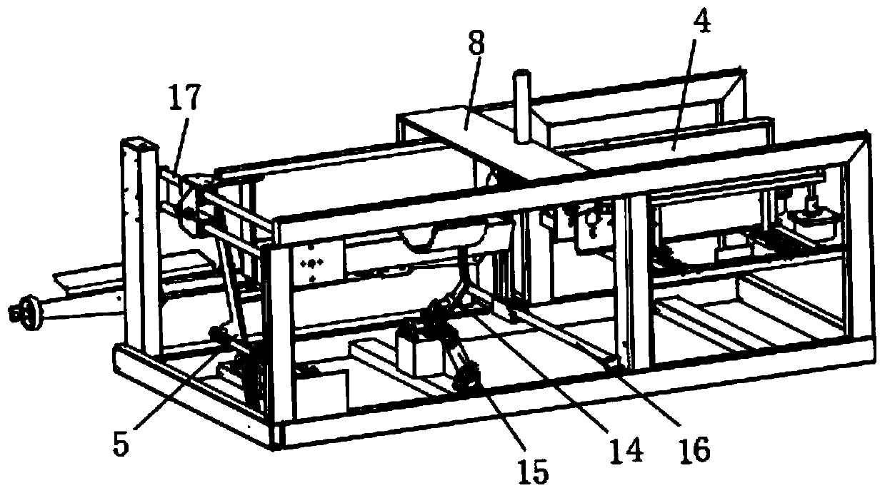
[0004] The purpose of the present invention is to provide a cutting machine for cutting structural wall pipes. The present invention arranges two belt conveying assemblies above the support cross bar, installs two threaded rods below the belt conveying assembly, and activates the moving motor To drive the threaded rod to rotate, the threaded rod drives the connecting longitudinal rod connected to it to move, and drives the belt conveying assembly to move through the connecting longitudinal rod, so that the two belt conveying assemblies move, and controls the rotation direction of the moving motor to control the rotation of the threaded rod The direction is controlled, so as to control the moving direction of the two belt conveying components, so as to realize the fixing and loosening of the structural wall pipes, and meet the cutting and placement of the structural wall pipes. The cutting machine is easy to adjust, and can be used when cutting the structural wall pipes. Fix it, so as to avoid the movement of the structural wall pipe when cutting, and solve the technical problem that the traditional structural wall pipe cutting machine cannot fix the structural wall pipe when cutting, and the cutting effect is poor;

Method used


Image

  • Cutting machine for cutting structural wall pipe
  • Cutting machine for cutting structural wall pipe
  • Cutting machine for cutting structural wall pipe

Examples


Embodiment Construction

[0036] The technical solutions of the present invention will be clearly and completely described below in conjunction with the embodiments. Apparently, the described embodiments are only some of the embodiments of the present invention, not all of them. Based on the embodiments of the present invention, all other embodiments obtained by persons of ordinary skill in the art without creative efforts fall within the protection scope of the present invention.

[0037] like Figure 1-7 As shown, a cutting machine for cutting structural wall pipes includes an installation frame 1, on which two support bars 2 are transversely fixed by welding, and the upper surface of the support bar 2 is fixedly installed with Two side plates 3, several support rollers 7 are installed between the two side plates 3, the several support rollers 7 are distributed at equal intervals, and the two ends of the support rollers 7 are respectively connected to the two side plates 3 in rotation Two threaded r...


PUM


Abstract

The invention discloses a cutting machine for cutting a structural wall pipe. The cutting machine comprises a mounting frame, wherein two supporting cross rods are fixed on the mounting frame, two belt conveying assemblies are arranged on the supporting cross rod, the belt conveying assemblies are in threaded connection with threaded rods through connecting longitudinal rods, a top supporting plate is fixed to the top of the mounting frame, a lifting air cylinder is fixed to the top supporting plate, a first motor mounting plate is fixed to an end of an output rod of the lifting air cylinder,a cutting motor is fixed to the first motor mounting plate, and a cutting blade is fixed to an output shaft end of the cutting motor. The cutting machine is convenient to adjust, structural wall pipescan be conveniently cut and fixed, and thereby the structural wall pipes are prevented from moving in the cutting process, the cutting effect is guaranteed, resistance of the structural wall pipe during moving is minimized, the service life of the cutting machine is guaranteed, the structural wall pipe can be automatically conveyed and collected, labor intensity is reduced, and production efficiency is improved.

Description

technical field [0001] The invention relates to the technical field of processing equipment for structural wall pipes, in particular to a cutting machine for cutting structural wall pipes. Background technique [0002] With the development of the modern mechanical processing industry, the requirements for cutting quality and precision are constantly improving, and the requirements for improving production efficiency, reducing production costs, and highly intelligent automatic cutting functions are also increasing; [0003] The patent document (CN208976939U) discloses a cutting machine for cutting structural wall pipes. When the cutting machine is in use, the structural wall pipes are placed in the base and only fixed by two moving push wheels. The stability is poor and the cutting cannot be guaranteed. As a result, when the structural wall pipe is moved, the resistance between the structural wall pipe and the base is large, and the loss of the pipe moving motor is large, and...

Claims


Application Information

Patent Timeline
Patent Type & Authority Applications(China)
IPC IPC(8): B26D1/18B26D3/16B26D7/06B26D7/32B26D7/02
CPCB26D1/18B26D3/16B26D7/02B26D7/0625B26D7/32B26D2007/0018B26D2007/013
Inventor 刘俊峰刘文江万刚曹操田祥军
Owner ANHUI JIELANTE NEW MATERIAL CO LTD
Learn More