
Cut-in direct-rotation mixed jet self-propelled nozzle

A self-propelled, jet technology, applied in the direction of drilling with liquid/gas jets, etc., can solve the problems such as the inability of the nozzle to move forward, the uneven bottom of the hole, etc., to enhance the shear and tensile damage effect, prevent energy loss, The effect of reducing energy loss

Inactive Publication Date: 2020-04-21
SOUTHWEST PETROLEUM UNIV +1
View PDF16 Cites 2 Cited by
  • Summary
  • Abstract
  • Description
  • Claims
  • Application Information

AI Technical Summary

Problems solved by technology

The jet flow produced by this structure has a good rock-breaking effect in the central area and the peripheral area of ​​the jet flow, and there will be an obvious low-velocity area between the two intervals, and there will be an obvious annular boss in the low-velocity area, resulting in uneven hole bottom. Flat, the problem that the nozzle cannot be pushed forward

Method used


Image

  • Cut-in direct-rotation mixed jet self-propelled nozzle
  • Cut-in direct-rotation mixed jet self-propelled nozzle
  • Cut-in direct-rotation mixed jet self-propelled nozzle

Examples


Embodiment

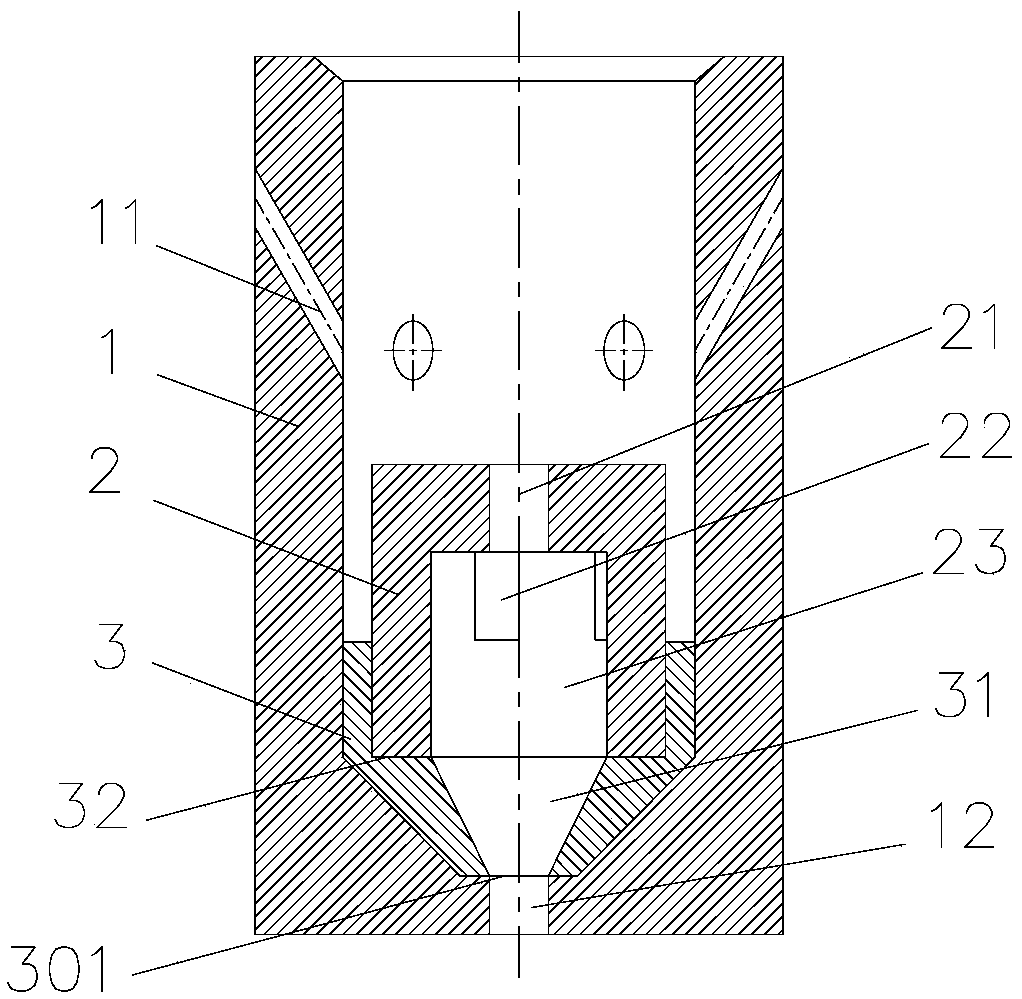
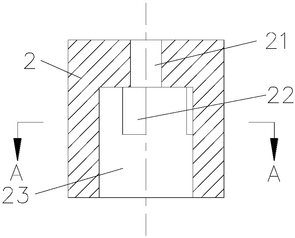
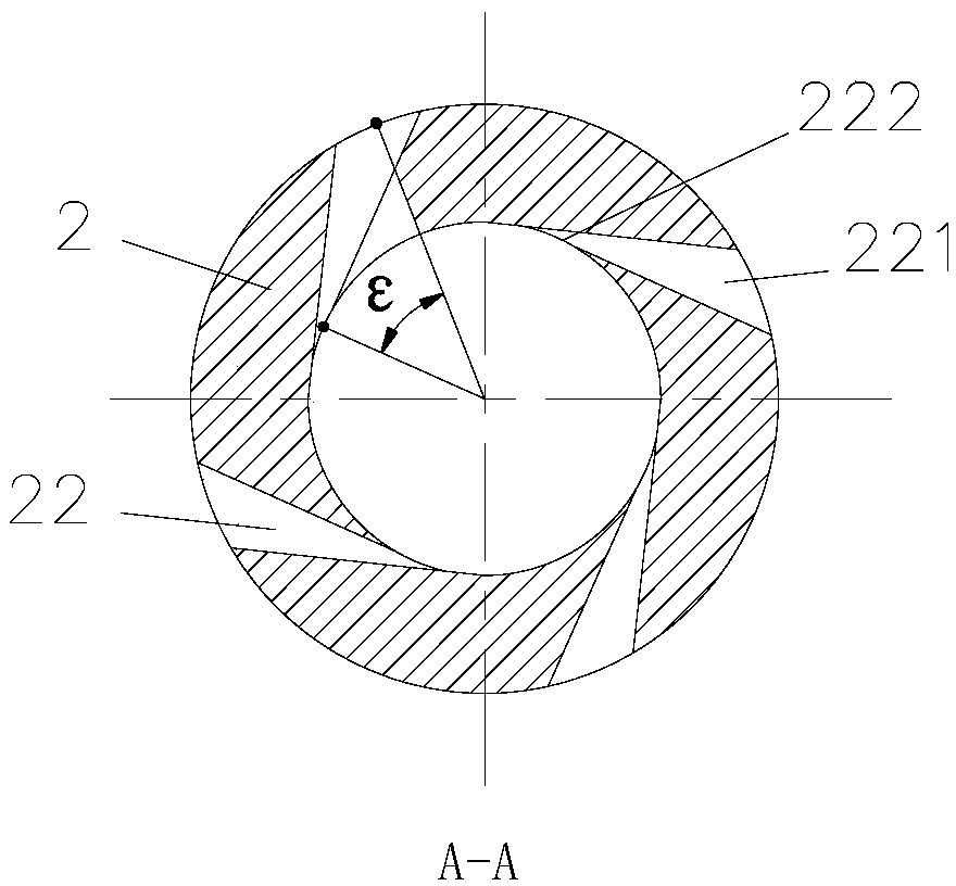
[0047] An embodiment of the present invention provides a cut-in direct-rotating mixed-jet self-advancing nozzle. see Figure 1-4 , the nozzle is composed of a mixed fluid 2, a mixed fluid seat 3, and a nozzle housing 1. The mixing body 2 is provided with a central hole 21 , a mixing chamber 23 and four cut-in grooves 22 . The central hole 21 is used to form a straight jet flow in the mixed flow chamber 23 , and the cut-in groove 22 forms a swirling jet flow in the mixed flow chamber 23 . The nozzle also includes a mixed fluid seat 3, on which a receiving groove 32 and a fluid channel 31 are arranged. The nozzle also includes a nozzle housing 1, and the nozzle housing 1 is provided with a rear nozzle 11 and a front nozzle 12. The mixed fluid 2, the mixed fluid seat 3, and the nozzle housing 1 are fixedly connected by means of interference fit.

[0048] In this example, the shape of the cutout 221 and the cutout 222 of the groove 22 is rectangular, and the shape and size of th...


PUM


Abstract

The invention discloses a cut-in direct-rotation mixed jet self-propelled nozzle, and belongs to the technical field of oilfield oil production engineering. The nozzle comprises a flow mixing body, and a flow mixing cavity, a central hole communicating with the flow mixing cavity and at least two cut-in grooves communicating with the flow mixing cavity are formed in the flow mixing body; and the central hole is used for forming a liquid straight flow in the flow mixing cavity, the cut-in grooves are used for forming a liquid swirling flow in the flow mixing cavity, and the two jet flows form adirect-rotation mixed jet flow in the flow mixing cavity. The invention aims to provide the cut-in direct-rotation mixed jet self-propelled nozzle, which can break the rock in a reliable structure and a direct-rotation mixed jet mode, and improve the rock breaking efficiency while prolonging the service life of the nozzle.

Description

technical field [0001] The invention belongs to the technical field of oil production engineering in oil fields, and in particular relates to a cut-in straight-rotating mixed-jet self-advancing nozzle. Background technique [0002] In the actual production process, high-pressure jet technology, as a new rock-breaking technology, has been widely used. Typically, jet nozzles are used to generate high-pressure jets. Currently, jet nozzles commonly used in hydraulic drilling operations include multi-hole jet nozzles and rotating jet nozzles. [0003] The multi-hole jet nozzle is similar to the round-hole straight jet nozzle, and has a simple structure and is easy to process. However, the porous jet nozzle has a large energy transmission distance, and the rock is broken by impact, and the energy utilization rate is low, and the impact area of ​​the porous jet at the bottom of the hole is not uniform, and the formed holes are irregular, which is not conducive to the removal of c...

Claims


Application Information

Patent Timeline
IPC IPC(8): E21B7/18
CPCE21B7/18
Inventor 付必伟张春亮杨迎新
Owner SOUTHWEST PETROLEUM UNIV
Learn More