Magnetic pump bearing box structure
A bearing box and magnetic pump technology, applied in the direction of pumps, pump components, non-variable capacity pumps, etc., can solve the problems of insufficient bearing capacity of the bearing box, the inability to drive the magnetic pump stably, and the leakage of lubricating oil in the bearing box. The effect of preventing oil leakage, improving oil leakage prevention, and improving the oil return structure
- Summary
- Abstract
- Description
- Claims
- Application Information
AI Technical Summary
Problems solved by technology
Method used
Image

Examples
Embodiment 1
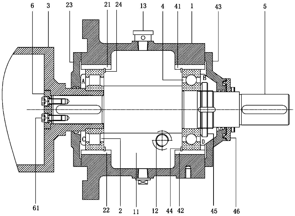
[0023] see figure 1 , the figure shows a magnetic pump bearing housing structure provided by Embodiment 1 of the present invention, including: a bearing housing 1, a first rolling bearing 2, an outer magnetic rotor 3, a second rolling bearing 4, a drive shaft 5 and a drive shaft stop Plate 6, the inside of the bearing box 1 is provided with an oil chamber 11, the oil chamber 11 is provided with lubricating oil, the first rolling bearing 2 and the second rolling bearing 4 are fixedly installed at both ends of the bearing box 1, the first rolling bearing 2 and the second rolling bearing The second rolling bearing 4 is set on the drive shaft 5. The bearing box 1 above the first rolling bearing 2 is provided with a first horizontal oil return groove 21, and the lower bearing box 1 is provided with a second horizontal oil return groove 22. The second rolling bearing 4 The upper bearing case 1 is provided with a third horizontal oil return groove 41, the lower bearing case 1 is prov...
Embodiment 2
[0034] see figure 1 , the figure shows a magnetic pump bearing housing structure provided by Embodiment 2 of the present invention. On the basis of the above embodiment, this embodiment further makes the following technical solutions as improvements: the first rolling bearing 2 passes through the shaft The first bearing cover 23 and the first circlip 24 on both sides are fixedly installed in the bearing housing, the first bearing cover 23 is fixedly installed on the end face of the bearing housing 1, and the first circlip 24 is clamped on the Inside the bearing housing 1.
[0035] One side of the first rolling bearing is installed in the mounting hole in the bearing box body through the first elastic circlip used for the hole, and the other side is pressed by the first bearing gland.
Embodiment 3
[0037] see figure 1 , the figure shows a magnetic pump bearing box structure provided by Embodiment 3 of the present invention. On the basis of the above embodiments, this embodiment further makes the following technical solutions as improvements: the second rolling bearing 4 passes through the shaft The second bearing cover 43 and the second circlip 44 on both sides are fixedly installed in the bearing housing 1, the second bearing cover 43 is fixedly installed on the end surface of the bearing housing 1, and the second circlip 44 is clamped. Connected to the bearing housing 1.
[0038]One side of the second rolling bearing is installed in the mounting hole in the bearing box body through the second elastic circlip used for the hole, and the other side is pressed by the second bearing gland. The second rolling bearing is mounted on the drive shaft with an interference fit
PUM
 Abstract
Description
Claims
Application Information
 - R&D
- Intellectual Property
- Life Sciences
- Materials
- Tech Scout
- Unparalleled Data Quality
- Higher Quality Content
- 60% Fewer Hallucinations
Browse by: Latest US Patents, China's latest patents, Technical Efficacy Thesaurus, Application Domain, Technology Topic, Popular Technical Reports.
© 2025 PatSnap. All rights reserved.Legal|Privacy policy|Modern Slavery Act Transparency Statement|Sitemap|About US| Contact US: help@patsnap.com