
Aero-engine part comprehensive test bed and test method

A comprehensive test bench and aero-engine technology, applied in the field of test systems, can solve the problems of inaccurate testing, high cost, and low testing efficiency, and achieve the effects of high measurement efficiency, low cost, and low process difficulty

Active Publication Date: 2020-04-21
湖南汉能科技有限公司
View PDF8 Cites 9 Cited by
  • Summary
  • Abstract
  • Description
  • Claims
  • Application Information

AI Technical Summary

Problems solved by technology

[0004] The present invention provides a comprehensive test bench for the aerodynamic performance and flow caused by anti-icing of an aero-engine test piece, which can test the aerodynamic performance and the flow caused by anti-icing on one test bench, and solve the problem of inaccurate testing and low test efficiency in existing test benches. high cost problem

Method used


Image

  • Aero-engine part comprehensive test bed and test method
  • Aero-engine part comprehensive test bed and test method
  • Aero-engine part comprehensive test bed and test method

Examples


Embodiment 1

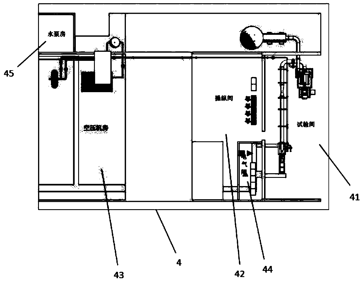
[0030] A test piece aerodynamic performance test device, such as figure 1 As shown, it includes a test piece mounting system 1, a main airflow piping system 2, and an anti-icing induced flow system 3.

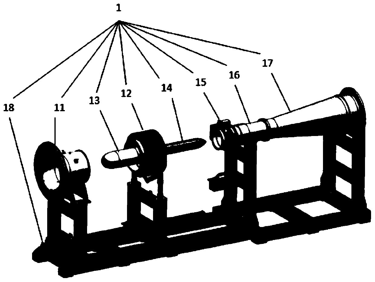
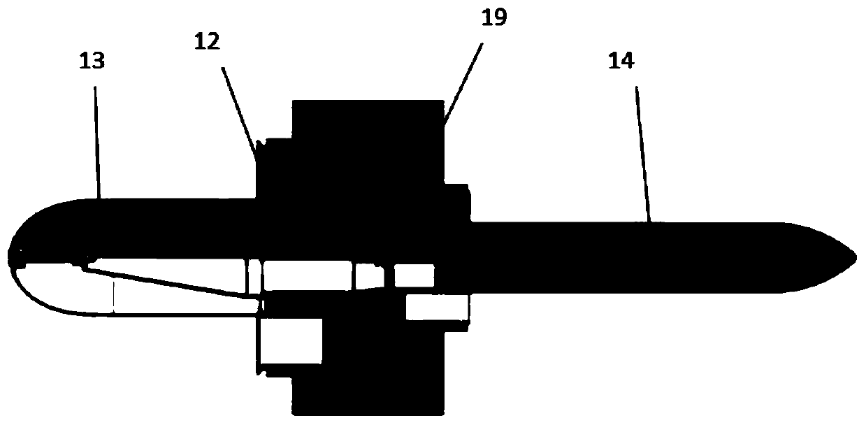
[0031] like image 3 As shown, the test piece installation system includes a test piece installation mechanism 12, an intake shroud 11, an intake cone assembly 13, an exhaust cone assembly 14, an exhaust straight pipe 16, a rotation measurement mechanism 15 and an expansion section 17, and the installation Mounting support 18 for the above components. The intake air shroud, the test piece installation mechanism 12, the rotation measurement mechanism 15, the exhaust straight pipe 16 and the expansion section 17 are connected in sequence to form a circular tubular shape, and the intake cone assembly 13 and the exhaust cone assembly 14 are arranged in the pipe. The front fairing 11 and the intake cone assembly 13 form an annular straight pipe section; the rear exhaust cone assem...

Embodiment 2

[0053] The present embodiment provides a comprehensive test bench test method for aero-engine parts, and the specific method is as follows:

[0054] When the aerodynamic performance measurement test of the test piece is performed, the interface of the anti-icing bleed air pipe is closed, and the ambient air enters the test piece through the intake duct and is discharged through the main airflow duct. There are 6 temperature measurement points, 4 static pressure measurement points and 12 total pressure measurement points on the intake duct to measure the air temperature, static pressure and total pressure entering the test piece. After the air flows through the test piece, it enters the rotating measuring device. The rotating measuring device is equipped with 3 sets of pressure measuring probes. Each set of probes includes 5 total pressure and 1 static pressure measuring point. The data acquisition system reserves 3 total pressure channels and 1 There are three static pressure ...


PUM


Abstract

An aero-engine part comprehensive test bed comprises a test piece mounting system, a main airflow pipeline system and an anti-icing air entraining flow system. The test piece mounting system comprisesan annular straight pipe section, a test piece mounting mechanism, a rotary measuring mechanism, an exhaust straight pipe section and an expansion section which are connected in sequence, the annularstraight pipe section comprises an air inlet fairing and an air inlet cone arranged inside the air inlet fairing, and a pressure testing device is arranged on the air inlet fairing; the test piece mounting mechanism is used for mounting a test piece; the rotary measuring mechanism and the exhaust straight pipe section are sequentially connected to form a straight pipe, the exhaust cone assembly is installed in the straight pipe, and the rotary measuring mechanism is provided with a total pressure probe and a static pressure measuring hole; the rear part of the straight exhaust pipe section isconnected with an expansion section; the main airflow pipeline system is connected to the rear end of the test piece mounting system and is used for extracting air out of the test piece; and the anti-icing air entraining flow system is connected to the test piece mounting system through an anti-icing air entraining interface. The test bed can meet two test items, and has the advantages of low cost and high test precision.

Description

technical field [0001] The invention relates to a test system for aero-engine components, in particular to a test bench capable of testing the aerodynamic performance of aero-engine particle separators and the flow caused by anti-icing. Background technique [0002] The working conditions of aero-engines are very harsh, and they are in a working state of high temperature, high pressure and high-speed rotation. In order to improve the performance, reliability and life of aero-engines, it is necessary to fully grasp the temperature, pressure, corrosion, and clearance of aero-engines under different working conditions. and stress, etc. In order to master the above data, it is usually necessary to test the aero-engine on the test bench, including parts and system tests, and the whole machine test. [0003] The particle separator is an important component installed at the inlet of an aero-engine to prevent damage to engine components, increased fuel consumption and reduced engin...

Claims


Application Information

Patent Timeline
Patent Type & Authority Applications(China)
IPC IPC(8): G01M15/14G01M15/02
CPCG01M15/02G01M15/14
Inventor 廖利华郭斌
Owner 湖南汉能科技有限公司
Learn More