Shiftable large-range capacitive coupling type non-contact conductivity measuring device and method

A non-contact conductance, measuring device technology, applied in the direction of material resistance, etc., can solve the problems of inconvenient application of multi-channel conductance detection, frequency selection limitation, difficulty in resonance adjustment, etc., and achieves small measurement requirements, high sensitivity, convenient and applicable. Effect

Active Publication Date: 2020-04-21
SHANGHAI JIAO TONG UNIV
View PDF12 Cites 3 Cited by
  • Summary
  • Abstract
  • Description
  • Claims
  • Application Information

AI Technical Summary

Problems solved by technology

However, such devices and methods can only work at a specific resonance frequency, not only the frequency selection is limited, but also the resonance adjustment is difficult. When the resonance point is adjusted inaccur

Method used


Image

  • Shiftable large-range capacitive coupling type non-contact conductivity measuring device and method
  • Shiftable large-range capacitive coupling type non-contact conductivity measuring device and method
  • Shiftable large-range capacitive coupling type non-contact conductivity measuring device and method

Examples


Embodiment 1

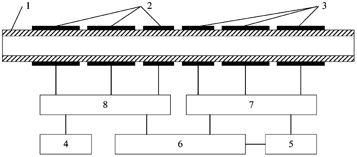
[0036] Such as figure 1As shown, this embodiment provides a capacitively coupled non-contact conductivity measurement device with a wide range of shiftable gears, including an insulating measurement pipeline 1, an excitation electrode module 2, a receiving electrode module 3, an AC excitation source 4, and a voltage detection module 5 , a control unit 6, a receiving electrode analog switch 7 and an excitation electrode analog switch 8. The excitation electrode module 2 is installed at one end of the insulated measurement pipeline 1 , and the receiving electrode module 3 is installed at the other end of the insulated measurement pipeline 1 . The common end of the excitation electrode analog switch 8 is connected to the AC excitation source 4; the channel end of the excitation electrode analog switch 8 is connected to the excitation electrode module 2 installed on the outer wall of the insulating measurement pipeline 1; the channel end of the receiving electrode analog switch 7 ...

Embodiment 2

[0056] The basic structure and principle of this embodiment are the same as those of the first embodiment, the difference is that the excitation electrode module 2 has only one excitation electrode, and the reception electrode module 3 uses three reception electrodes. The receiving electrode is arranged on one side of the exciting electrode, forming a semi-nested electrode arrangement. Only one receiving electrode is in the working state at any time, and the control unit 6 controls the receiving electrode analog switch 7 to switch on different receiving electrodes to realize gear switching. The receiving electrode and the excitation electrode of the electrode form a higher gear, and the number of receiving electrodes is the number of gears. The length of each receiving electrode in the electrode module is the same, and is also the same as that of the excitation electrode.

[0057] The measurement process of this embodiment is:

[0058] Before measurement: measure each electr...


PUM

PropertyMeasurementUnit
Outer diameteraaaaaaaaaa
The inside diameter ofaaaaaaaaaa

Abstract

The invention relates to a shiftable large-range capacitive coupling type non-contact conductivity measuring device and a shiftable large-range capacitive coupling type non-contact conductivity measuring method. The measuring device comprises an insulation measurement pipeline, an excitation electrode module, a receiving electrode module, an alternating current excitation source, a voltage detection module and a control unit, wherein the receiving electrode module comprises at least two receiving electrodes; the excitation electrode module comprises at least two excitation electrodes, the number of the excitation electrodes is the same as that of the receiving electrodes, the measuring device further comprises an excitation electrode analog switch and a receiving electrode analog switch, the receiving electrode analog switch is connected with the control unit and the voltage detection module, and the excitation electrode analog switch is connected with the control unit; and the controlunit sequentially performs gear shifting measurement or directly outputs the conductivity value of the solution in the insulation measurement pipeline according to the voltage value output by means of the voltage detection module according to a certain method. Compared with the prior art, the shiftable large-range capacitive coupling type non-contact conductivity measuring method has the advantages of high detection sensitivity, large measurement range and the like, and can be applied to multi-channel conductivity detection occasions.

Description

technical field [0001] The invention relates to a conductance detection technology, in particular to a capacitively coupled non-contact conductance measurement device and method capable of shifting gears in a wide range. Background technique [0002] Conductivity is one of the basic physical parameters of liquids, and the detection of conductivity plays an important role in the analysis of liquid components, distribution, concentration and other characteristic parameters. [0003] In the existing conductivity detection method, according to whether the electrode is in contact with the solution to be tested, it can be divided into contact conductivity detection and non-contact conductivity detection. The detection electrode of the contact conductivity detection method is in contact with the solution, which is prone to electrical polarization and electrochemical The problem of corrosion limits the application of this type of detection method; the non-contact conductometric dete...

Claims


Application Information

Patent Timeline
IPC IPC(8): G01N27/07
CPCG01N27/07
Inventor 刘伟文曹成喜张强王源豫梁子其
Owner SHANGHAI JIAO TONG UNIV
Why Eureka
Try Eureka