Identification system for V-CUT of circuit board

A V-CUT and identification system technology, applied in printed circuit testing, electronic circuit testing, etc., can solve the problems of manual inspection and easy missed inspection, and achieve the effect of improving yield rate, avoiding missed inspection, and improving inspection effect

Inactive Publication Date: 2020-04-21
CHONGQING KAIGE ELECTRONICS CO LTD
View PDF9 Cites 0 Cited by
  • Summary
  • Abstract
  • Description
  • Claims
  • Application Information

AI Technical Summary

Problems solved by technology

[0004] The present invention intends to provide an identification system for circuit board V-CUT, to solve the problem that manual detection is adopted when checking the V-CUT cutting situation on the circuit board at present, and the problem of missing detection is prone to occur

Method used


Image

  • Identification system for V-CUT of circuit board
  • Identification system for V-CUT of circuit board
  • Identification system for V-CUT of circuit board

Examples


Embodiment 1

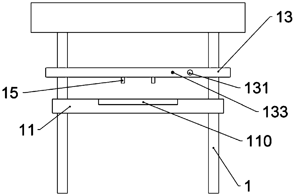
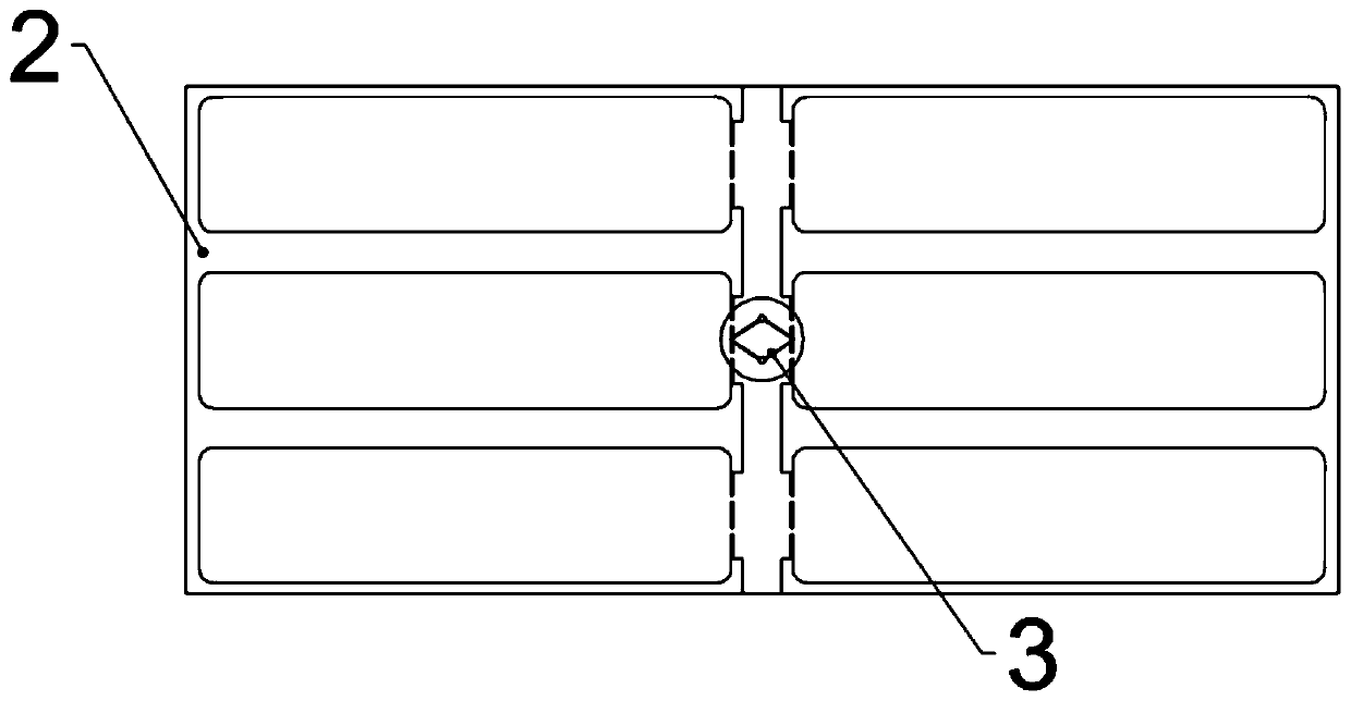
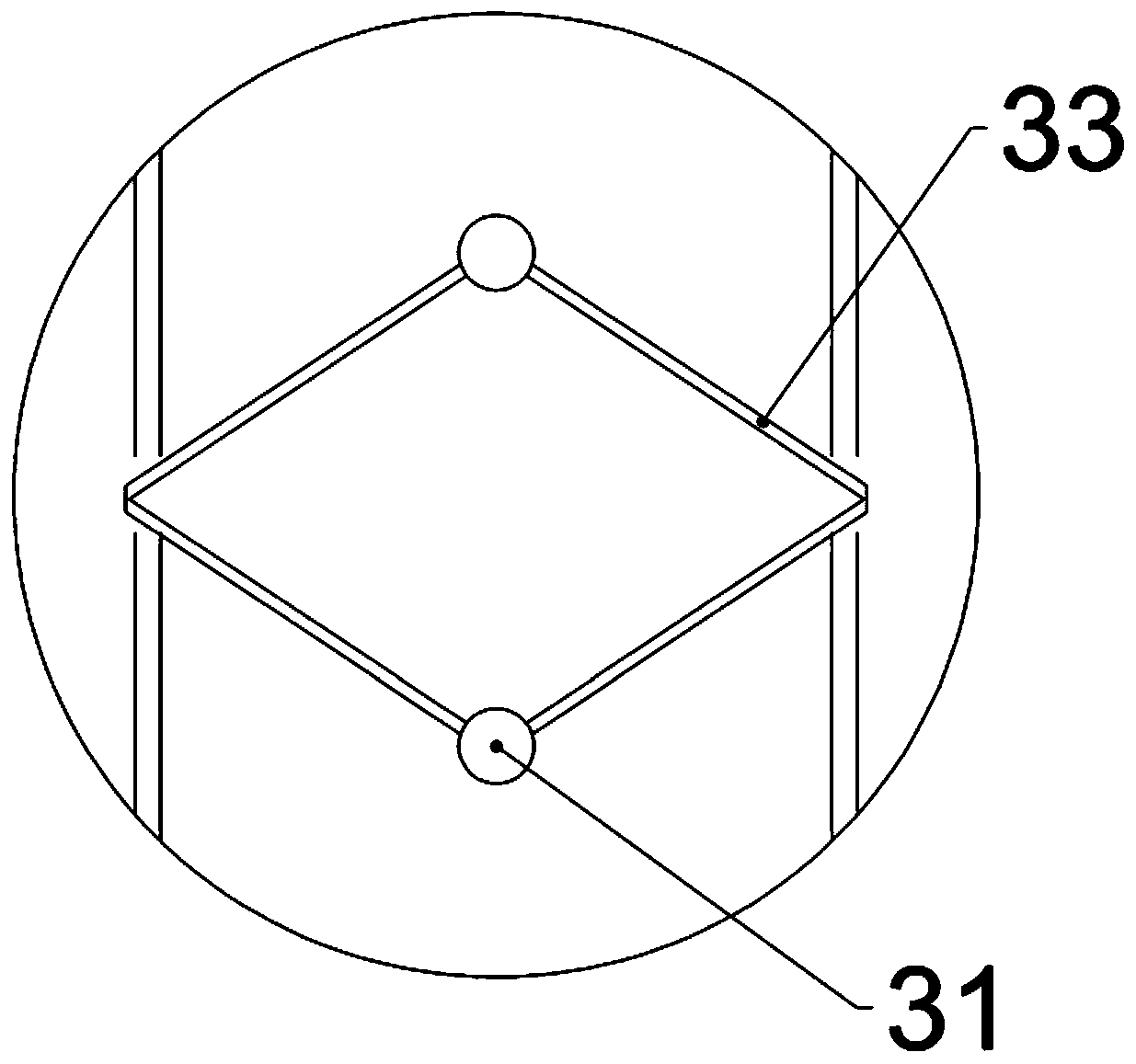
[0025] Basic as attached figure 1 Shown: the identification system for circuit board 2V-CUT, including a marking module, used to mark the circuit board 2 with the test wire 3, the test wire 3 includes a test line 33 and test points 31 at both ends of the test line 33, The test lead 3 passes through the preset V-CUT position;

[0026] Detection mechanism, including detection circuit, driver board 13, placement board 11 and indicator light, such as figure 1 As shown, the drive plate 13 and the placement plate 11 are installed on the frame 1, the placement plate 11 is fixedly arranged on the frame 1, the drive plate 13 slides with the frame 1, and an elastic member is arranged between the drive plate 13 and the placement plate 11 , the upper end of the elastic member is connected to the lower surface of the drive plate 13, and the lower end of the elastic member is connected to the upper surface of the placement plate 11. Specifically, the elastic member can be a compression spr...

Embodiment 2

[0041] The difference from Embodiment 1 is that a collection mechanism is also provided in this solution. The collection mechanism is located on one side of the placement plate 11 . The collection mechanism includes a collection box, and one side of the collection box is against the placement plate 11 .

[0042] A collection mechanism is provided to collect the circuit boards 2 that have passed the test. After the placement board 11 is offset against the collection box, after the circuit board 2 passes the test, the circuit board 2 can be directly pushed into the collection box. The operation is simple.

Embodiment 3

[0044] Considering that when the PCB boards are placed, they are usually stacked in the warehouse in the form of full boxes. When necessary, the full boxes of PCB boards are taken out from the warehouse and then processed. Since the PCB boards are stored in a stacked manner, it is not standardized. The picking behavior makes the stability of the PCB board stacking weakened, subject to slight vibration, the PCB board is prone to drop, and the PCB board is prone to damage.

[0045] The difference between this embodiment and the first and second embodiments is that it also includes a supervision subsystem, an identity verification terminal and multiple monitoring terminals. The identity verification terminal is set at the gate of the warehouse, and the warehouse managers need to pass the verification before they can open the warehouse to pick up the goods. The monitoring terminals are installed in the warehouse, and are respectively installed in multiple positions of the warehous...


PUM


Abstract

The invention relates to the technical field of circuit board production equipment. In order to solve the problem that detection omission is easy to occur when a manual detection mode is adopted to check the V-CUT cutting condition on a circuit board at present, the invention provides an identification system for V-CUT of a circuit board. The identification system comprises a marking module and adetection mechanism, wherein the marking module is used for marking a test wire for the circuit board, the test wire comprises a test line and test points at two ends of the test line, and the test wire passes through a preset V-CUT position; the detection mechanism comprises a detection circuit, a driving plate and a placement plate, conductive detection pieces are arranged at the two ends of thedetection circuit respectively, and the detection circuit further comprises an alarm module used for sending an alarm when the detection circuit is conducted; the detection circuit is arranged on thedriving plate, the driving plate is connected with the placement plate through a driving rod, and the driving plate can reciprocate up and down along the driving rod. According to the invention, missed detection can be avoided, and the yield of the circuit board is improved.

Description

technical field [0001] The invention relates to the technical field of circuit board production equipment, in particular to an identification system for circuit board V-CUT. Background technique [0002] Printed circuit boards are also called PCB boards, which use insulating boards as the base material and are cut to a certain size. At least one conductive pattern is attached to them as the substrate, and holes (such as component holes, fastening holes, metal Mounting holes such as mounting holes) are used to replace the chassis of electronic components in the past, and the electrical connection between component pins is realized through conductive patterns, pads and metallized vias on the substrate. After the printed circuit board is formed and processed, it is necessary to perform V-CUT cutting on the board with the process edge, so as to facilitate the board separation after the components are packaged. Therefore, in order to improve the yield rate of the circuit board, ...

Claims


Application Information

Patent Timeline
Patent Type & Authority Applications(China)
IPC IPC(8): G01R31/28
CPCG01R31/281
Inventor 余丕芳
Owner CHONGQING KAIGE ELECTRONICS CO LTD
Why Eureka
Try Eureka