Optical fiber slip ring for optical communication equipment

A fiber optic slip ring and optical communication technology, which is applied in the coupling of optical waveguide, light guide, optics, etc., can solve the problems of easy corrosion, corrosion damage and damage of optical fiber slip ring, so as to improve corrosion resistance, prevent corrosion damage, The effect of extending the service life

Inactive Publication Date: 2020-04-21
深圳市国扬通讯有限公司 +1
View PDF8 Cites 0 Cited by
  • Summary
  • Abstract
  • Description
  • Claims
  • Application Information

AI Technical Summary

Problems solved by technology

[0005] Aiming at the deficiencies of the prior art, the present invention provides an optical fiber slip ring for optical communication equipment, which has the advantages of insulation and corrosion resistance to the optical fiber slip ring, and solves the problem that the existing optical fiber slip ring does not have the function of insulation, resulting in When the optical fiber slip ring is in contact with the power supply, it is easy to introduce electricity into the optical fiber, causing a short circuit or even damage to the optical fiber. Problems with corrosion damage

Method used


Image

  • Optical fiber slip ring for optical communication equipment
  • Optical fiber slip ring for optical communication equipment
  • Optical fiber slip ring for optical communication equipment

Examples


Embodiment Construction

[0021] The following will clearly and completely describe the technical solutions in the embodiments of the present invention with reference to the accompanying drawings in the embodiments of the present invention. Obviously, the described embodiments are only some, not all, embodiments of the present invention. Based on the embodiments of the present invention, all other embodiments obtained by persons of ordinary skill in the art without making creative efforts belong to the protection scope of the present invention.

[0022] All components of the present invention are common standard components or components known to those skilled in the art, and their structures and principles can be known to those skilled in the art through technical manuals or through conventional experimental methods.

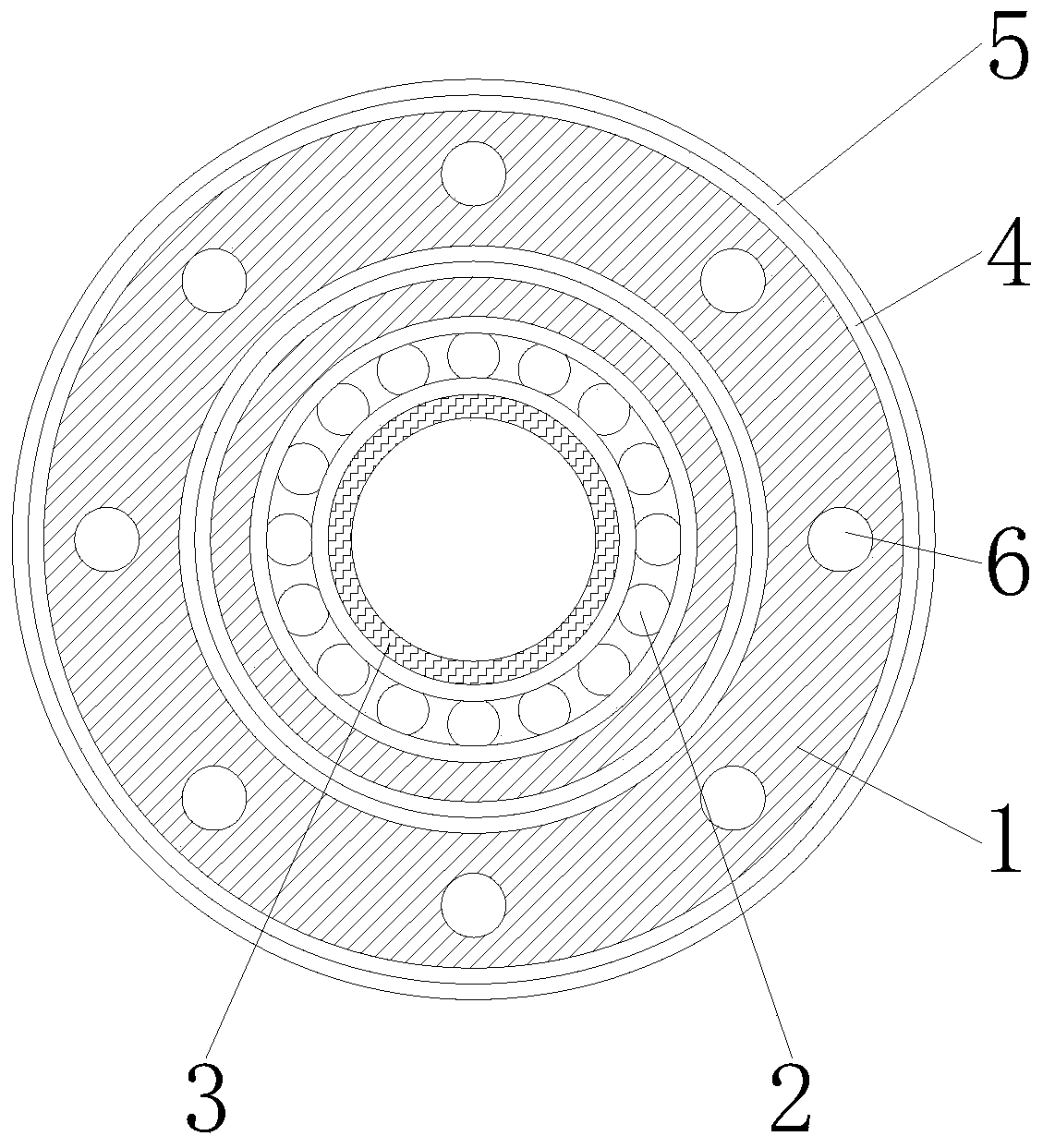
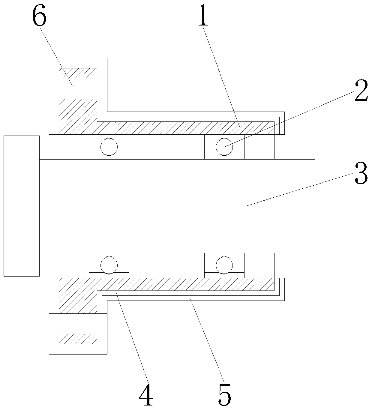
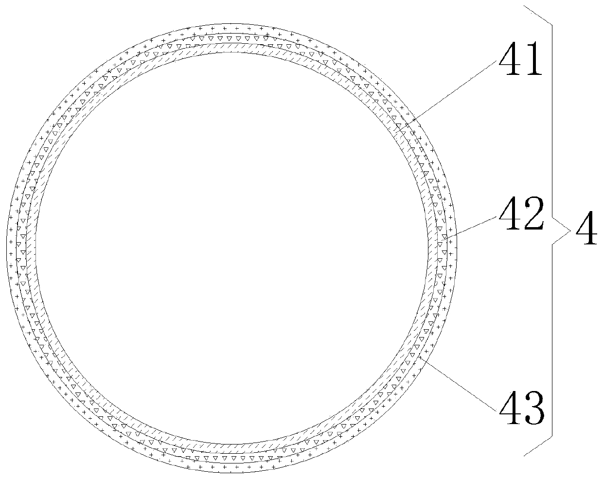
[0023] see Figure 1-4 , an optical fiber slip ring for optical communication equipment, comprising a slip ring stator 1, the front end and rear end of the inner wall of the slip ring st...


PUM


Abstract

The invention discloses an optical fiber slip ring for optical communication equipment, which comprises a slip ring stator, wherein bearings are fixedly connected to the front end and the rear end ofthe inner wall of the slip ring stator, the inner walls of the bearings are fixedly connected with a slip ring rotor, the surface of the slip ring stator is provided with an insulating layer, and a corrosion-resistant layer is arranged on the side, which is away from the slip ring stator, of the insulating layer. According to the invention, the advantages of insulation and corrosion resistance ofthe optical fiber slip ring are achieved through mutual cooperation of the bearings, the insulating layer, an insulating plastic layer, an insulating rubber layer, an insulating silica gel layer, thecorrosion-resistant layer, a phenolic resin paint layer, an epoxy resin coating layer and an inorganic zinc-rich paint layer; when the optical fiber slip ring is in contact with a power supply, the optical fiber slip ring can be effectively insulated, the problem that the optical fiber is short-circuited and even damaged due to the fact that electricity is conducted into the optical fiber is prevented, the service life of the optical fiber is prolonged, the corrosion resistance of the optical fiber slip ring is improved, the optical fiber slip ring is prevented from being corroded and damaged,and the service life of the optical fiber slip ring is prolonged.

Description

technical field [0001] The invention relates to the technical field of optical fiber slip rings, in particular to an optical fiber slip ring used in optical communication equipment. Background technique [0002] Slip rings are electrical components responsible for connecting, transmitting energy and signals to rotating bodies. According to the transmission medium, slip rings are divided into electric slip rings, fluid slip rings, and smooth rings. They can also be collectively referred to as "rotary communication" or "Swivel", the slip ring is usually installed at the center of rotation of the equipment, mainly composed of two parts: rotating and stationary, the rotating part is connected to the rotating structure of the equipment and rotates accordingly, called "rotor", and the stationary part is connected to the fixed part of the equipment The energy source of the structure, called the "stator". [0003] Optical fiber slip rings are required for the use of optical fibers ...

Claims


Application Information

Patent Timeline
Patent Type & Authority Applications(China)
IPC IPC(8): G02B6/38
CPCG02B6/3807G02B6/3894
Inventor 彭斌陈伟况艳汤志敏刘祖发张小勇
Owner 深圳市国扬通讯有限公司
Why Eureka
Try Eureka