
Array substrate, display panel, and electrical testing method

An array substrate and electrical testing technology, applied to circuits, electrical components, static indicators, etc., can solve the problems of undetectable panels, waste of materials, detection and discovery, etc.

Active Publication Date: 2021-05-07
WUHAN CHINA STAR OPTOELECTRONICS TECH CO LTD
View PDF8 Cites 0 Cited by
  • Summary
  • Abstract
  • Description
  • Claims
  • Application Information

AI Technical Summary

Problems solved by technology

When the gate insulating layer (gateinsulator, GI) film falls off between the gate layer and the active layer, the gate layer and the active layer will leak due to short circuit, resulting in abnormal horizontal lines on the display screen
However, due to the limited capacity of the electrical testing machine itself, it is impossible to detect the area with a distance of about five pixels on the left and right sides of the panel. Therefore, this problem cannot be detected by the electrical testing machine immediately after the thin film transistor manufacturing process is completed. waste of

Method used


Image

  • Array substrate, display panel, and electrical testing method
  • Array substrate, display panel, and electrical testing method
  • Array substrate, display panel, and electrical testing method

Examples


Embodiment Construction

[0017] The following will clearly and completely describe the technical solutions in the embodiments of the present invention with reference to the drawings in the embodiments of the present invention. Apparently, the described embodiments are only some of the embodiments of the present invention, but not all of them. Based on the embodiments of the present invention, all other embodiments obtained by those skilled in the art without creative efforts fall within the protection scope of the present application.

[0018] The following description of the embodiments refers to the accompanying drawings to illustrate specific embodiments in which the invention may be practiced. The directional terms mentioned in the present invention, such as [top], [bottom], [front], [back], [left], [right], [inside], [outside], [side], etc., are only for reference The orientation of the attached schema. Therefore, the directional terms used are used to illustrate and understand the present inve...


PUM


Abstract

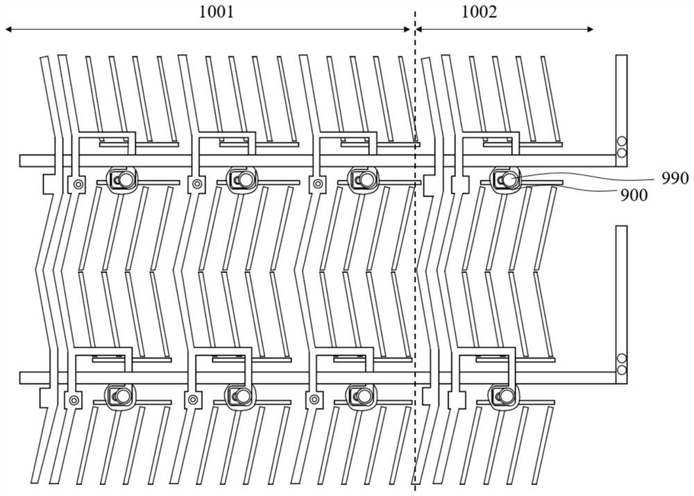
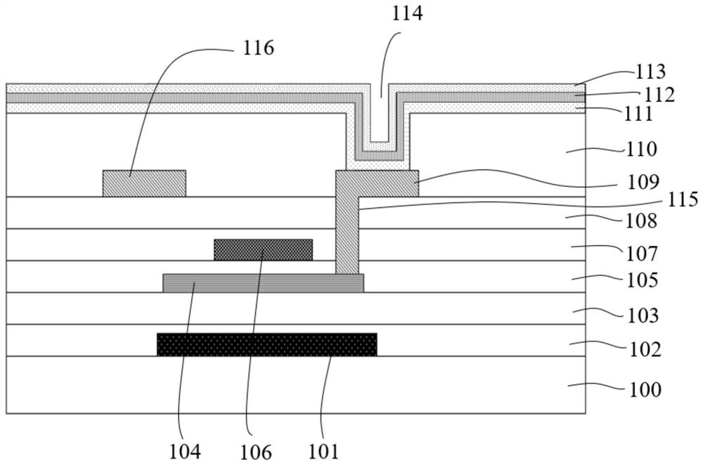
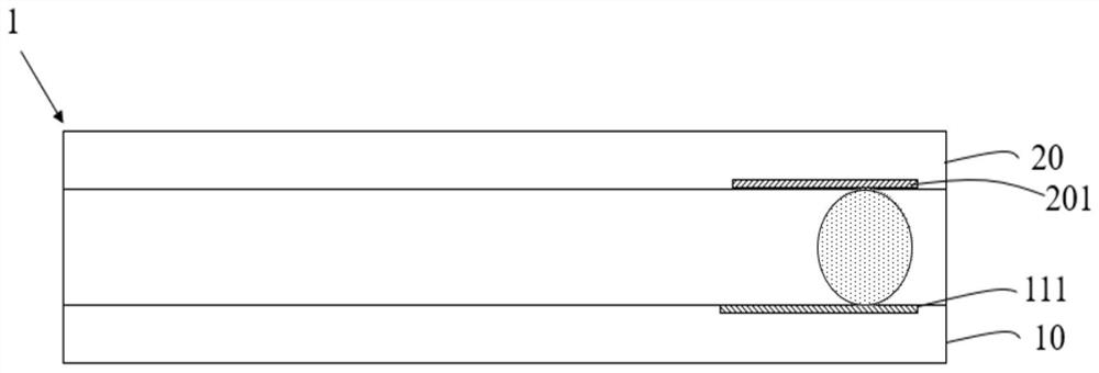
An array substrate, a display panel, and an electrical testing method, the array substrate comprising: a substrate including a display area and an electrical testing area; a thin film transistor layer disposed on the substrate, the thin film transistor layer comprising a The test thin film transistor in the electrical test area, wherein the test thin film transistor includes an active layer, a gate layer, and an electrode layer, and one end of the active layer is connected to the first electrode of the electrode layer, so The other end of the active layer is suspended; the planarization layer is arranged on the electrode layer of the thin film transistor, wherein the planarization layer is provided with a first via hole corresponding to the first electrode of the electrode layer; the common An electrode layer is disposed on a side of the planarization layer away from the electrode layer, and the common electrode layer is connected to the first electrode of the electrode layer through the first via hole.

Description

【Technical field】 [0001] The invention relates to the field of display technology, in particular to an array substrate, a display panel and an electrical testing method for the array substrate. 【Background technique】 [0002] With the gradual popularity of low temperature polysilicon (LTPS) liquid crystal display panels, the circuit design of the thin film transistor layer is becoming more and more refined, and the pixel density (pixels per inch, PPI) of small-sized panels is also gradually increasing. Display panels require multiple processes in the Array segment. In the manufacturing process, there is a non-functional dummy thin-film transistor on the outermost periphery of the thin-film transistor layer, which is only used as a reference boundary when printing polyimide (PI) film, and does not play a display role. When the gate insulating layer (gateinsulator, GI) thin film falls off between the gate layer and the active layer, the gate layer and the active layer will le...

Claims


Application Information

Patent Timeline
Patent Type & Authority Patents(China)
IPC IPC(8): G09G3/00H01L27/12G02F1/13G02F1/1362G02F1/1368
CPCG02F1/1309G02F1/1362G02F1/1368G09G3/006H01L27/1214
Inventor 安喜锋潘鹏鹏
Owner WUHAN CHINA STAR OPTOELECTRONICS TECH CO LTD
Learn More