Control chip mounting base of control system

A technology for controlling chips and control systems, applied in electrical components, electrical solid devices, circuits, etc., can solve the problems of uneven force on the chip, troublesome operation, damage, etc., to achieve easy replacement, easy disassembly, and avoid pin looseness. Effect

Inactive Publication Date: 2020-04-21
PAGMAN TECH (TAICANG) CO LTD
View PDF0 Cites 6 Cited by
  • Summary
  • Abstract
  • Description
  • Claims
  • Application Information

AI Technical Summary

Problems solved by technology

[0003] Existing electronic chips are directly fixed to the PCB board with glue, and it is troublesome to replace the chip when the chip needs to be replaced. Moreover, due to the fixing effect of the glue, it is easy to cause damage to the chip due to uneven force when the chip is removed.

Method used


Image

  • Control chip mounting base of control system
  • Control chip mounting base of control system
  • Control chip mounting base of control system

Examples


Embodiment 1

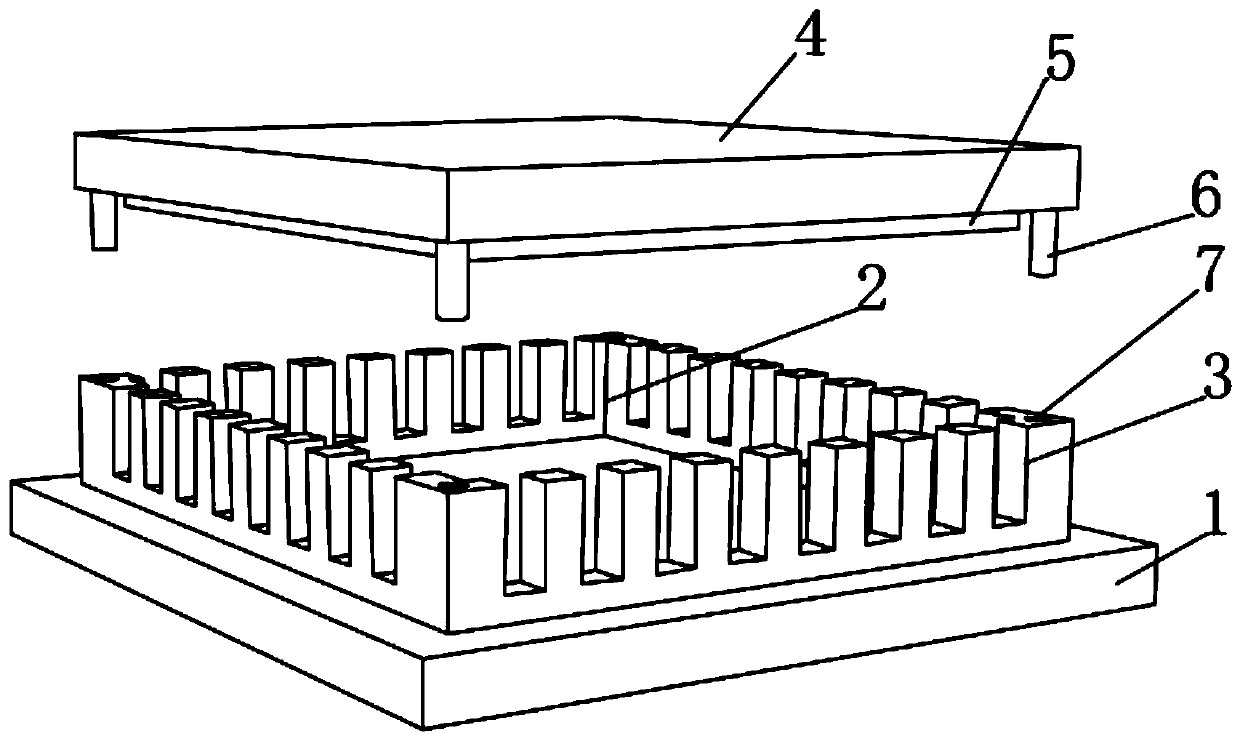
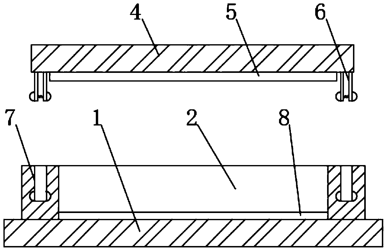
[0028] As attached Figure 1-2 The control chip mounting seat of a control system of the present invention shown includes a base 1 and a mounting plate fixedly connected to the upper end of the base 1. A mounting groove 2 is excavated inside the mounting plate, and a plurality of evenly distributed mounting plates are excavated around the mounting plate. Pin slot 3, a cover plate 4 is provided above the base 1. The four corners of the lower end of the cover plate 4 are fixedly connected with positioning posts 6, and the four corners of the upper end of the mounting plate are cut with positioning slots 7 matching the positioning posts 6. The lower end of the cover plate 4 is fixedly connected with a heat conduction plate 5, and a plurality of evenly distributed heat dissipation holes are excavated on the cover plate 4. The heat conduction plate 5 can promptly guide the heat generated by the chip in the working process upward, and then discharge it upward through the heat dissipat...

Embodiment 2

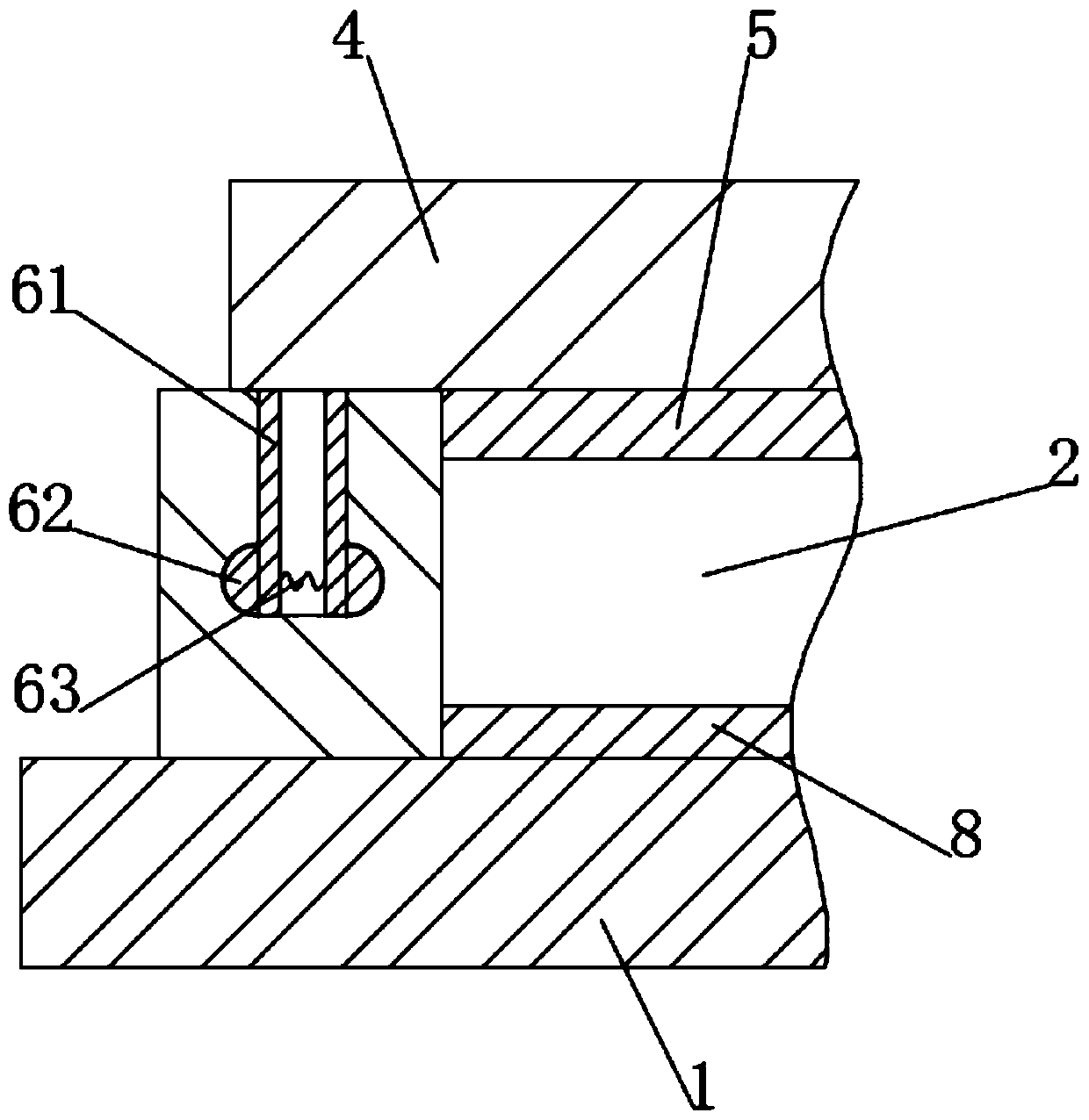
[0032] As attached image 3 The shrapnel 61 can also be arranged in a cylindrical structure on the outer surface, and the cross section of the inner surface of the shrapnel 61 is set up with a small lower and a large slope, which effectively ensures that when the positioning pillar 6 is inserted into the positioning groove 7, the two shrapnel 61 are squeezed After pressing, there can be a certain inward squeezing space, which is convenient for insertion and extraction.

[0033] When installing the chip, first align the pins of the chip with the pin slot 3, place the chip in the mounting slot 2, and then align the positioning column 6 on the cover 4 with the positioning slot 7 and press down so that the chip is fixed in the mounting slot. In slot 2, when disassembling the chip, first press the pressing rod 10 manually or through the frame of the back shape, and then pull the cover plate 4 upward through the pull ring 9 to separate the cover plate 4 from the mounting plate, which ca...


PUM


Abstract

The invention relates to a control chip mounting base of a control system and belongs to the chip mounting field. The control chip mounting base of the control system. The control chip mounting base of the control system comprises a base and a mounting plate fixedly connected to the upper end of the base; a mounting groove is formed in the mounting plate; a plurality of pin grooves which are uniformly distributed are formed in the periphery of the mounting plate; a cover plate is arranged above the base; positioning columns are fixedly connected to four corners of the lower end of the cover plate; positioning grooves matched with the positioning columns are formed in the four corners of the upper end of the mounting plate; each positioning column comprises two elastic sheets fixedly connected with the cover plate; bulges are fixedly connected to the outer ends of the lower sides of the two elastic sheets; compression springs are fixedly connected to the ends, close to each other, of the two elastic pieces; pressing rods are fixedly connected to the left upper end and the right upper end of the base and located on the outer side of the mounting plate; a pull ring is rotationally connected to the upper end of the cover plate; so that the chip is convenient to mount and dismount; the replacement of the chip is facilitated; and damage to the chip in a replacement process is effectively reduced.

Description

Technical field [0001] The present invention relates to a chip mounting base, in particular to a control chip mounting base of a control system. Background technique [0002] Chips, also known as microcircuits, microchips, and integrated circuits. Refers to silicon chips containing integrated circuits, which are small in size and are often part of computers or other electronic equipment. It is a general term for semiconductor component products. [0003] The existing electronic chip is directly fixed to the PCB board by glue, and the operation is troublesome when the chip needs to be replaced, and due to the fixing effect of the glue, the chip is easily damaged due to uneven force applied when the chip is removed. Summary of the invention [0004] The purpose of the present invention is to provide a control chip mounting seat for a control system in order to overcome the shortcomings of the prior art. [0005] In order to achieve the above objective, the technical solution adopted b...

Claims


Application Information

Patent Timeline
Patent Type & Authority Applications(China)
IPC IPC(8): H01L23/04H01L23/10H01L23/12H01L23/16H01L23/367
CPCH01L23/04H01L23/10H01L23/12H01L23/16H01L23/367H01L23/32H01L23/40H01L23/4093
Inventor 王刚唐弇冬周皓
Owner PAGMAN TECH (TAICANG) CO LTD
Why Eureka
Try Eureka