
Current type control system and method for three-state step-down switching power supply

A switching power supply and control system technology, applied in the direction of conversion equipment without intermediate conversion to AC, can solve rare, complex loop control, complex control and other problems, achieve small inductor size, small device electrical stress, transient response quick effect

Inactive Publication Date: 2020-04-21
CHENGDU YICHONG WIRELESS POWER TECH CO LTD
View PDF6 Cites 0 Cited by
  • Summary
  • Abstract
  • Description
  • Claims
  • Application Information

AI Technical Summary

Problems solved by technology

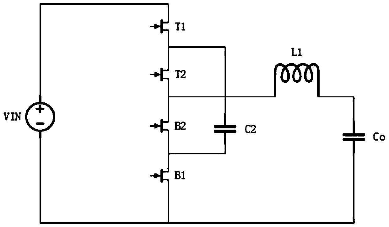
[0004] Through the theoretical research of 3-level BUCK, it can be seen that the voltage-type pulse width mode (PWM) control is very simple, but it also has two shortcomings that are difficult to overcome: one is that it is difficult to improve the transient response, and the other is that it requires a more complicated loop control to keep the voltage on C2 constant at one-half of the input voltage
Since the current mode 3-level BUCK cannot work in pure peak current mode (PCM) or valley current mode (VCM) like the traditional BUCK, it needs to switch between PCM and VCM as the duty cycle changes, so the control is relatively difficult. Complicated, and relevant reports and studies are relatively rare at present

Method used


Image

  • Current type control system and method for three-state step-down switching power supply
  • Current type control system and method for three-state step-down switching power supply

Examples


Embodiment Construction

[0025] The present invention will be further described below in conjunction with the accompanying drawings.

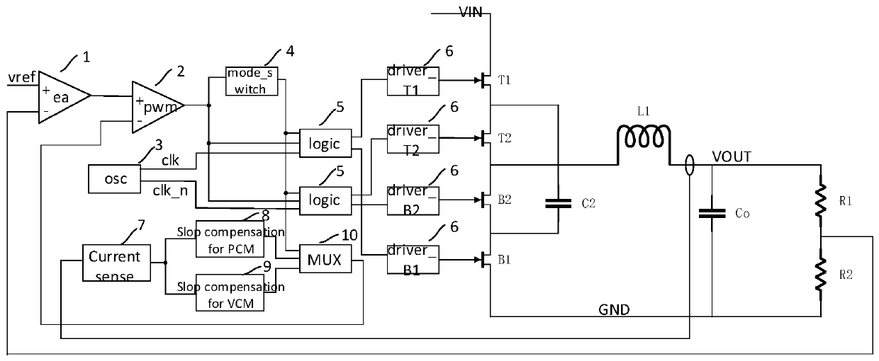
[0026] A current-type three-state step-down switching power supply control system, including a first upper power transistor T1 and a corresponding first lower power transistor B1 arranged on a voltage source circuit, and also includes a first upper power transistor T1 and a first lower power transistor B1 arranged on a voltage source circuit. The second upper power tube T2 between the lower power tubes B1 and the corresponding second lower power tube B2, a mode selector (modeswitch) 4, and a logic control module 6;

[0027] The mode selector 4 is used to select the working state of the peak current mode PCM or the valley current mode VCM; the mode selection can be realized by using the existing technology;

[0028] The logic control module 6 is used to control the opening and closing of the power tube under the peak current mode PCM and the valley current mode VCM; the...


PUM


Abstract

The invention discloses a current type control system and method for a three-state step-down switching power supply. The method comprises the following steps that: a first upper power tube and a corresponding first lower power tube are arranged on a voltage source loop, and a second upper power tube and a corresponding second lower power tube are arranged between the first upper power tube and thefirst lower power tube; the working states of a peak current mode and a valley current mode are set; in the peak current mode, the first upper power tube is turned on when a first rising edge arrives, and the second upper power tube is turned on when a second rising edge arrives; in the valley current mode, the first lower power tube is turned on when the first rising edge arrives, and the secondlower power tube is turned on when the second rising edge arrives; and the conduction time of the power tubes is controlled by adopting PWM signals. The current control method of the three-state step-down switching power supply is realized. The control method has the advantages of faster transient response, smaller device electrical stress and smaller inductance size.

Description

technical field [0001] The invention relates to the technical field of switching power supplies, in particular to a current-type three-state step-down switching power supply control system and method. Background technique [0002] Due to the application requirements of high power density power supply, compared with the traditional BUCK topology, the three-state step-down (3-level BUCK) switching power supply has smaller device electrical stress and smaller inductor size under the same input and output range and power application conditions. advantage, began to receive more attention and research. [0003] Such as figure 1 The topological structure of 3-level BUCK is shown. Compared with the traditional structure, power transistor T2, power transistor B2, and capacitor C2 are added. In order to obtain the minimum device electrical stress and the smallest inductor size, it is necessary to keep the voltage on C2 as the input half of the voltage. [0004] Through the theoreti...

Claims


Application Information

Patent Timeline
Patent Type & Authority Applications(China)
IPC IPC(8): H02M3/10
CPCH02M3/10
Inventor 谢毅潘思铭金学成
Owner CHENGDU YICHONG WIRELESS POWER TECH CO LTD
Learn More