
CAN bus simulation monitoring method
A CAN bus, analog monitoring technology, applied in the bus network, data exchange through path configuration, digital transmission system, etc., can solve the problem of poor real-time performance of CAN communication modules or CAN cards, insufficient functions of triggering and controlling data sending and receiving, and data shielding and receiving functions Insufficient and other problems, to improve adaptability, increase trigger control data sending and receiving, and meet the needs of use
Patent Information
- Authority / Receiving Office
- CN · China
- Patent Type
- Applications(China)
- Current Assignee / Owner
- Publication Date
- 2020-04-21
Smart Images
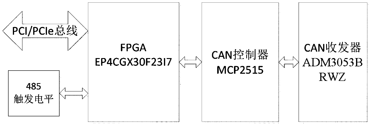
Figure 1 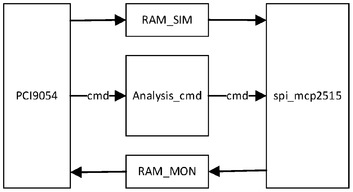
Figure 2 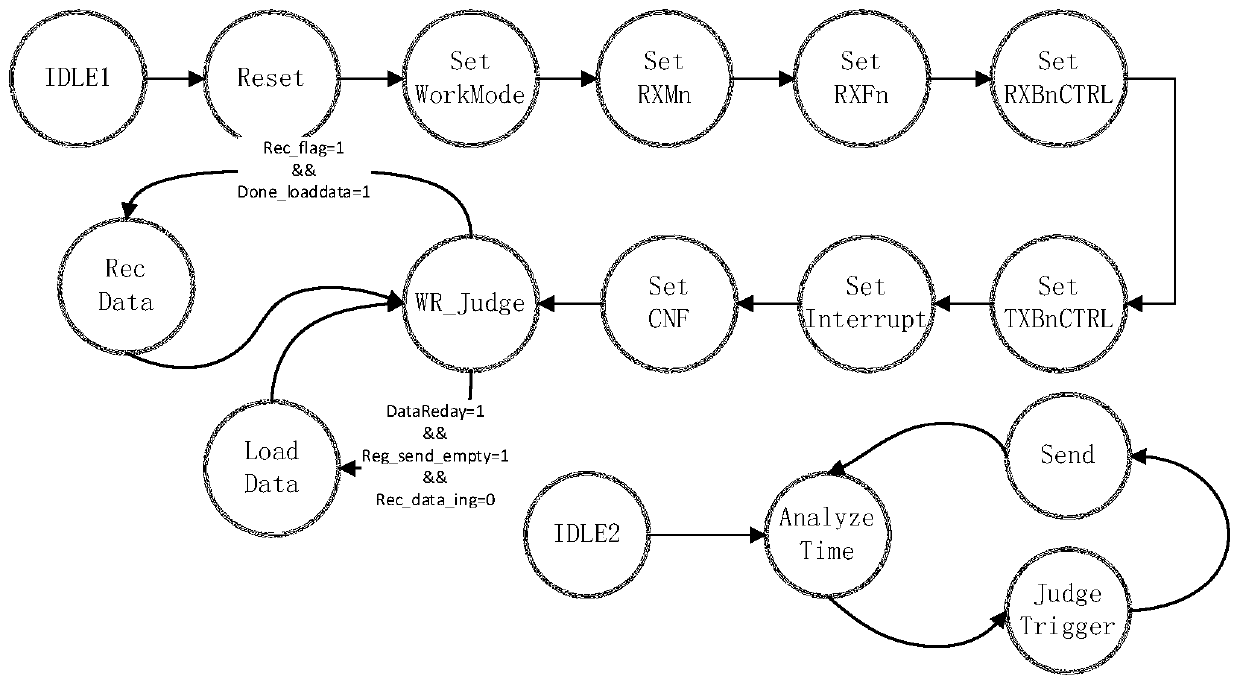
Figure 3
Abstract
Description
technical field
[0001] The invention belongs to the technical field of CAN bus communication engineering, and in particular relates to a CAN bus simulation monitoring method. Background technique
[0002] With the rapid development of information technology, users have higher and higher real-time requirements for CAN bus-based communication. At the same time, there are more requirements for the functions of sending and receiving data at regular intervals and triggering control of sending and receiving data, especially in industries with high reliability and safety requirements. However, most of the current mature CAN communication modules or boards have real-time performance at the ms level, and do not have the functions of sending and receiving data at regular intervals or controlling data sending and receiving through triggering, which limits the performance of some products in the CAN bus communication industry.
[0003] The mainstream CAN communication modules or boards...
Examples
Embodiment 1
[0100] In order to solve the problems of poor real-time performance of the current CAN communication module or CAN card, insufficient function of trigger control data transmission and reception, lack of timing transmission function, insufficient data shielding reception function, etc., this embodiment provides a set of design schemes for CAN bus data transmission and reception, such as figure 1 The FPGA logic design is shown:
[0101] The innovation points are:
[0102] 1. Use the MCP2515 to have three data buffers. During the initialization process after power-on, write the data to be sent to the three buffers first; during the sending process, monitor the status of the three buffers and find any buffer After the data is read, new data is written to the buffer immediately (while data is written to this buffer, any one of the other two buffers is in the state of sending data). The ability to realize this feature depends on the fact that the MCP2515 has three relatively indepe...