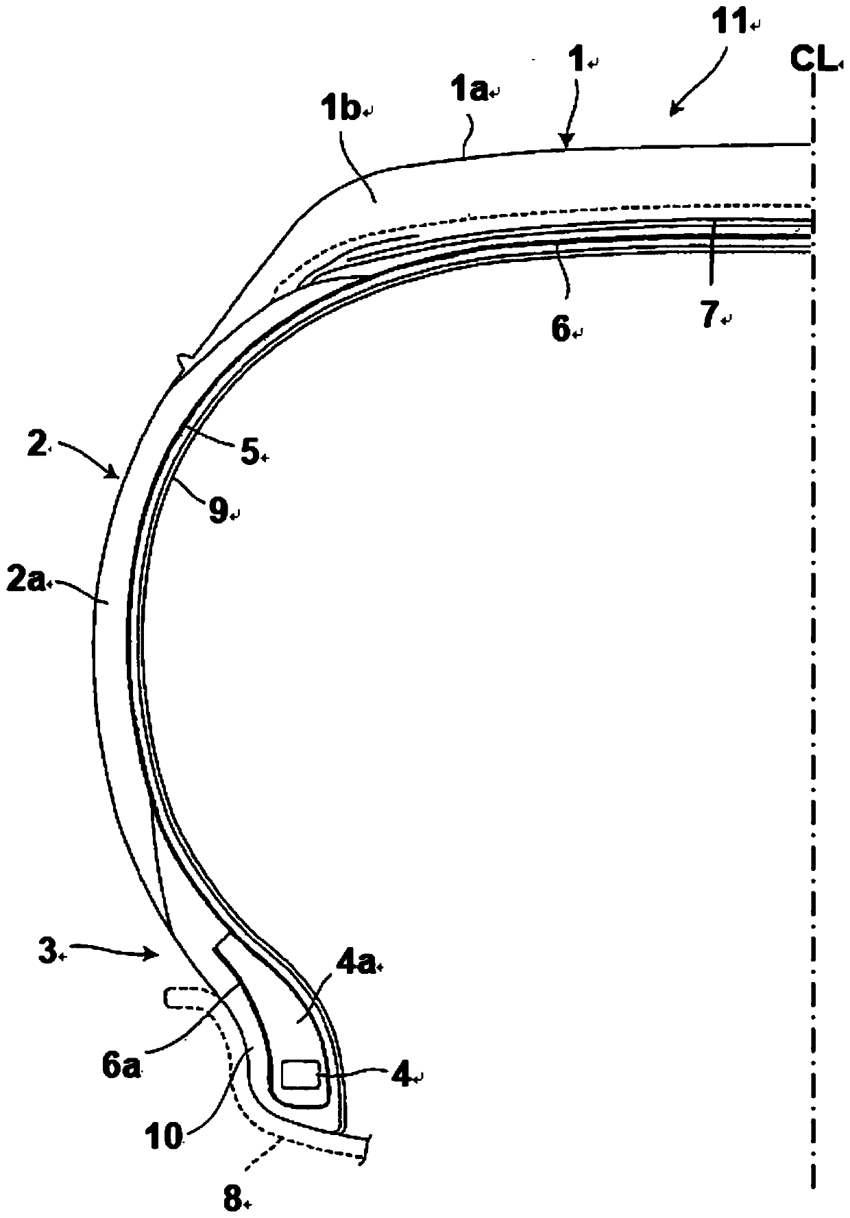
Pneumatic tire

A technology of pneumatic tires and tires, which is applied to the reinforcement layer of pneumatic tires, special tires, tire parts, etc., can solve the problems of reduced wet road grip and extended braking distance, etc. The effect of road performance

Inactive Publication Date: 2020-04-21
BRIDGESTONE CORP
View PDF9 Cites 0 Cited by
  • Summary
  • Abstract
  • Description
  • Claims
  • Application Information

AI Technical Summary

Problems solved by technology

As a result, there are problems of reduced grip on wet roads and extended braking distances

Method used


Image

  • Pneumatic tire
  • Pneumatic tire
  • Pneumatic tire

Examples


manufacture example 1

[0142] [Production Example 1: Production of Modified Styrene-Butadiene Copolymer Rubber]

[0143] To a dry and nitrogen-purged 800-mL pressure-resistant glass vessel, 1,3-butadiene in cyclohexane and styrene in cyclohexane were added to contain 67.5 g of 1,3-butadiene and 7.5 g of styrene. Then, 0.6 mmol of 2,2-ditetrahydrofurylpropane was added, 0.8 mmol of n-butyllithium was further added as a polymerization initiator, and then polymerization was performed at 50° C. for 1.5 hours. The polymerization conversion in the reaction was approximately up to 100%. To the polymerization reaction system, 0.72 mmol of modifier was added and allowed to react at 50° C. for 30 minutes. After that, 2 mL of a 5% by mass solution of 2,6-di-tert-butyl-p-cresol:BHT in 2-propanol was added, and the reaction was quenched. The resulting product was dried according to a conventional method, and a modified styrene-butadiene copolymer rubber was obtained.

[0144] [production of tire]

[0145] T...


PUM

PropertyMeasurementUnit
specific surface areaaaaaaaaaaa

Abstract

Provided is a pneumatic tire that achieves both wet performance when in contact with low-temperature road surfaces and low rolling resistance, said pneumatic tire characterized by comprising: a treadobtained from a rubber composition containing specific amounts of a natural rubber and a modified styrene-butadiene copolymer rubber, as well as a reinforcing filler and a thermoplastic resin; and a rubber chafer obtained from a rubber composition containing carbon black that has a large particle size and exhibits specific physical properties.

Description

technical field [0001] The present invention relates to a pneumatic tire including a carcass portion and a tread portion having improved wet grip and low rolling resistance. Background technique [0002] In recent years, energy-saving and high-efficiency tires have been developed to meet social demands for energy conservation. Measures to develop such tires from the viewpoints of weight reduction of tires, prolongation of product life and "realization of low loss", or selective reduction of rolling resistance of tires have been studied. [0003] Along with the demand for further improvement in fuel efficiency of tires, not only reduction in rolling resistance of tire treads but also tire components used in carcass components such as carcass-coated rubber, belt-coated rubber , reduction of rolling resistance of squeegee rubber between the plies, cushion rubber between tread and belt, bead filler and rubber chafer. [0004] The main measure to reduce rolling resistance is to...

Claims


Application Information

Patent Timeline
Patent Type & Authority Applications(China)
IPC IPC(8): B60C1/00B60C11/00B60C15/06C08C19/25C08K3/04C08K3/36C08L7/00C08L9/06C08L101/12
CPCB60C1/00B60C11/00B60C15/06C08C19/25C08K3/04C08K3/36C08L7/00C08L9/06C08L101/12C08F236/10C08C19/44C08C19/22C08L15/00C08L57/02C08F236/06C08F212/08C08F4/48C08F2/06B60C1/0016B60C9/02C08J7/12C08K2201/006C08L23/20C08L47/00C08L93/04C08L2205/03
Inventor 坪田毅
Owner BRIDGESTONE CORP
Why Eureka
Try Eureka