Gas sensor element and gas sensor

A technology for gas sensors and components, applied in instruments, scientific instruments, electrochemical variables of materials, etc., can solve the problems of not easy to improve responsiveness, thickening of layer thickness, etc.

Active Publication Date: 2020-04-21
DENSO CORP
View PDF14 Cites 0 Cited by
  • Summary
  • Abstract
  • Description
  • Claims
  • Application Information

AI Technical Summary

Problems solved by technology

For this reason, if the protective layer corresponding to the corner of the element is thickened...

Method used


Image

  • Gas sensor element and gas sensor
  • Gas sensor element and gas sensor
  • Gas sensor element and gas sensor

Examples


Embodiment approach 1

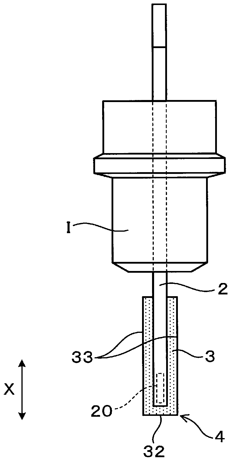
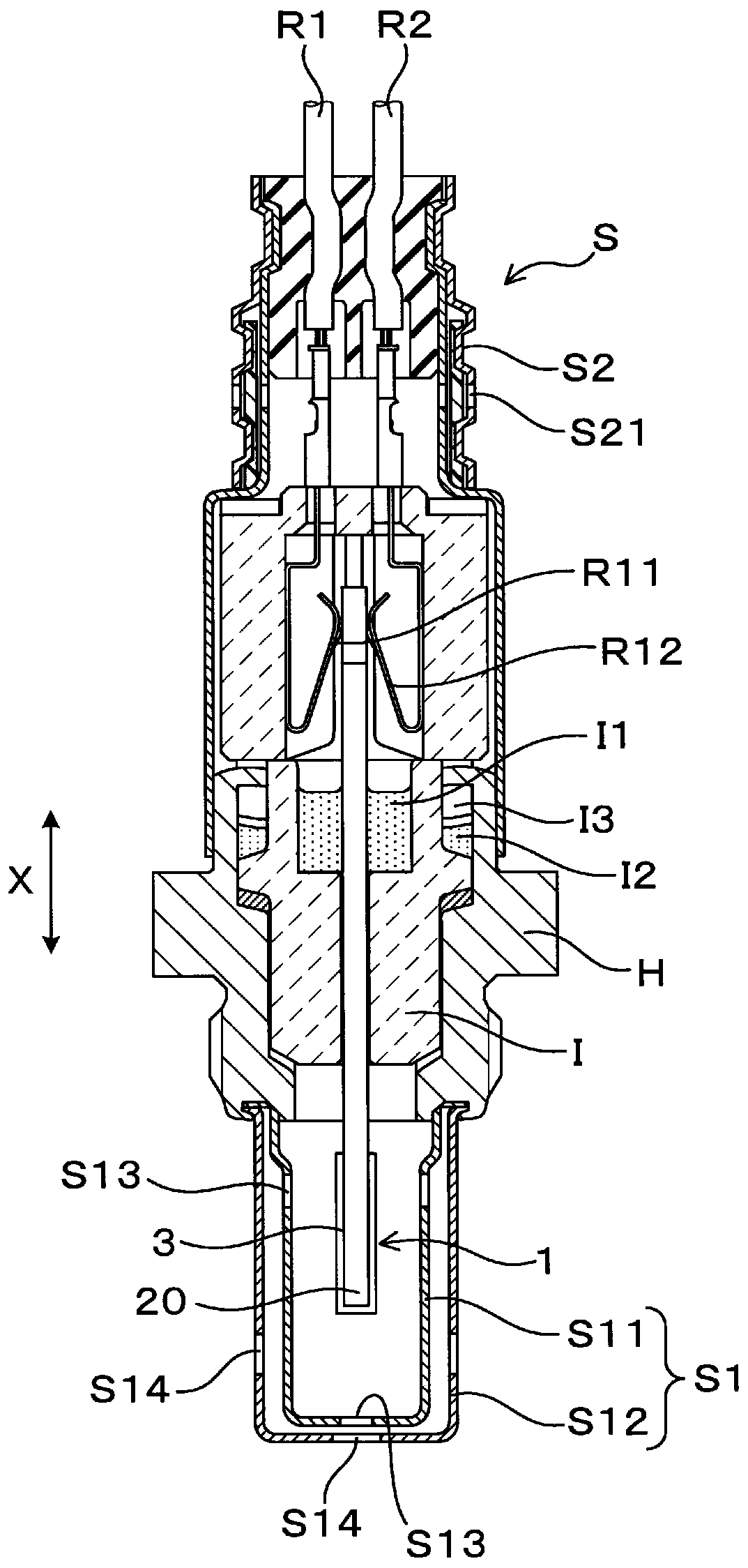
[0044] Below, refer to Figure 1 to Figure 6 Embodiments of the gas sensor element and the gas sensor will be described. figure 1 , figure 2 The gas sensor element 1 shown consists of image 3 The main part of the shown gas sensor S is supported by a cylindrical case H on its outer periphery in a state of being inserted through a cylindrical insulator (insulator) I. The gas sensor S can be applied to, for example, an exhaust purification system of an automobile engine, and the gas sensor element 1 detects a specific gas concentration in exhaust gas as a gas to be measured. Specifically, it can be used for an oxygen sensor that detects an oxygen concentration, an air-fuel ratio sensor that detects an air-fuel ratio (that is, A / F) based on an oxygen concentration, and the like.

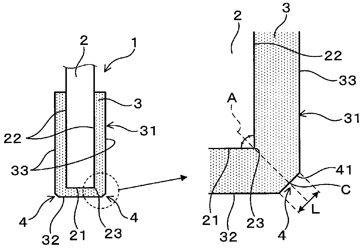
[0045] exist figure 1 , figure 2 Among them, the gas sensor element 1 includes a long plate-shaped element body 2 and a porous protective layer 3 that protects the surface of the element body 2...

Embodiment approach 2

[0111] refer to Figure 16 ~ Figure 18 Embodiment 2 of a gas sensor element and a gas sensor will be described. In the gas sensor element 1 of Embodiment 1 described above, the protective layer 3 has a rectangular parallelepiped outer shape substantially similar to the rectangular parallelepiped element main body 2 , but the opposing two surfaces may not necessarily be arranged in parallel. For example, the end surface 32 or the side surface 33 of the protective layer 3 may be inclined relative to the front end surface 21 or the side surface 22 of the element body 2, and the angle formed by the end surface 32 and the side surface 33 may not be a right angle.

[0112] The basic structures of the gas sensor element 1 and the gas sensor S of this embodiment are the same as those of the first embodiment described above, and description thereof will be omitted.

[0113] In addition, among the reference numerals used after the second embodiment, the same reference numerals as those...

Embodiment approach 3

[0131] refer to Figure 21 Embodiment 3 of the gas sensor element and the gas sensor will be described. In the gas sensor element 1 described in each of the above-mentioned embodiments, water repellency can be further improved by imparting hydrophobicity to the protective layer 3 . In order to impart hydrophobicity to the protective layer 3, for example, as described in the above-mentioned Patent Document 1, the protective layer 3 may have a structure having a hydrophobic film on the surface in addition to the structure in which the vapor film (Ledenfrost) phenomenon can occur. .

[0132] The basic structures of the gas sensor element 1 and the gas sensor S of this embodiment are the same as those of the first embodiment described above, and description thereof will be omitted.

[0133] in particular, Figure 21 The structure of the protective layer 3 shown is the same as the above Figure 16 The same is true for the second embodiment shown. The end surface 32 and the side...


PUM


Abstract

A gas sensor element (1) for detecting a specific gas component in a monitored gas is provided with: an elongated-plate-shaped element body (2) having a gas detection part (20) at an end section at the distal end surface (21) side in a longitudinal direction (X); and a porous protective layer (3) provided so as to cover the periphery of the end section at the end surface side of the element body.In a cross section including two adjacent surfaces from the end surface and from among the multiple side surfaces (22) connected to the end surface, the protective layer is shaped in such a manner that an outer surface (31) opposite an element corner section (23) where said two surfaces meet has a corner section (4). The corner section has a ratio (D/L) of 1.5 or more, where D represents an assumed diameter of a waterdrop (W) contained in the monitored gas in the usage environment, and L represents the effective length of the corner section in the cross section.

Description

[0001] Cross-references to related applications [0002] This application is based on Japanese Patent Application No. 2017-159692 filed on August 22, 2017, the contents of which are cited here. technical field [0003] The present invention relates to a gas sensor element covered with a porous protective layer and a gas sensor including the gas sensor element. Background technique [0004] The exhaust system of an automobile engine is equipped with a gas sensor that detects a specific exhaust gas, and emission reduction is achieved by performing combustion control based on the detection result of the gas sensor. The gas sensor has a long plate-shaped gas sensor element housed in the cover, and the gas sensor element is protected from the intrusion of water droplets and harmful substances by a porous protective layer provided on the outer surface. The gas sensor element is configured by incorporating a heater portion in an element body provided with a gas sensing portion. ...

Claims


Application Information

Patent Timeline
IPC IPC(8): G01N27/41G01N27/409
CPCG01N27/4077G01N27/4067G01N27/4072G01N27/409
Inventor 毛利友隆今田将太竹内亨
Owner DENSO CORP
Why Eureka
Try Eureka