A display module bonding assembly line

An assembly line and display module technology, applied in lamination devices, lamination auxiliary operations, chemical instruments and methods, etc., can solve the problems of dripping, dispensing position deviation, low work efficiency, etc., and achieve thorough cleaning , the dispensing position is accurate, and the effect of ensuring flatness

Active Publication Date: 2021-09-03
上海芯辉电子股份有限公司
View PDF3 Cites 0 Cited by
  • Summary
  • Abstract
  • Description
  • Claims
  • Application Information

AI Technical Summary

Problems solved by technology

[0002] During the assembly process of the display module, dispensing of glue is required in the lamination process of the display. The traditional assembly method is completed manually, and the work efficiency is low. Therefore, the display module lamination assembly equipment has been developed. Assembled in the way that mechanization greatly improves the assembly efficiency, the current display module lamination assembly line has the following defects:
[0003] The existing display module lamination assembly line is equipped with an automatic dispensing device, and glue is automatically applied during the assembly process, which improves the assembly speed. If the amount of glue dispensed is small, the assembly of the display module will not be firm. Therefore, the amount of glue dispensed Can be more or less, after the amount of glue is too much, some of the remaining glue will drop onto the assembly line, and the dried glue will remain on the workbench of the assembly line, causing the next module to be unable to be placed stably, and making the dispensing The position is deviated

Method used


Image

  • A display module bonding assembly line
  • A display module bonding assembly line
  • A display module bonding assembly line

Examples


Embodiment 1

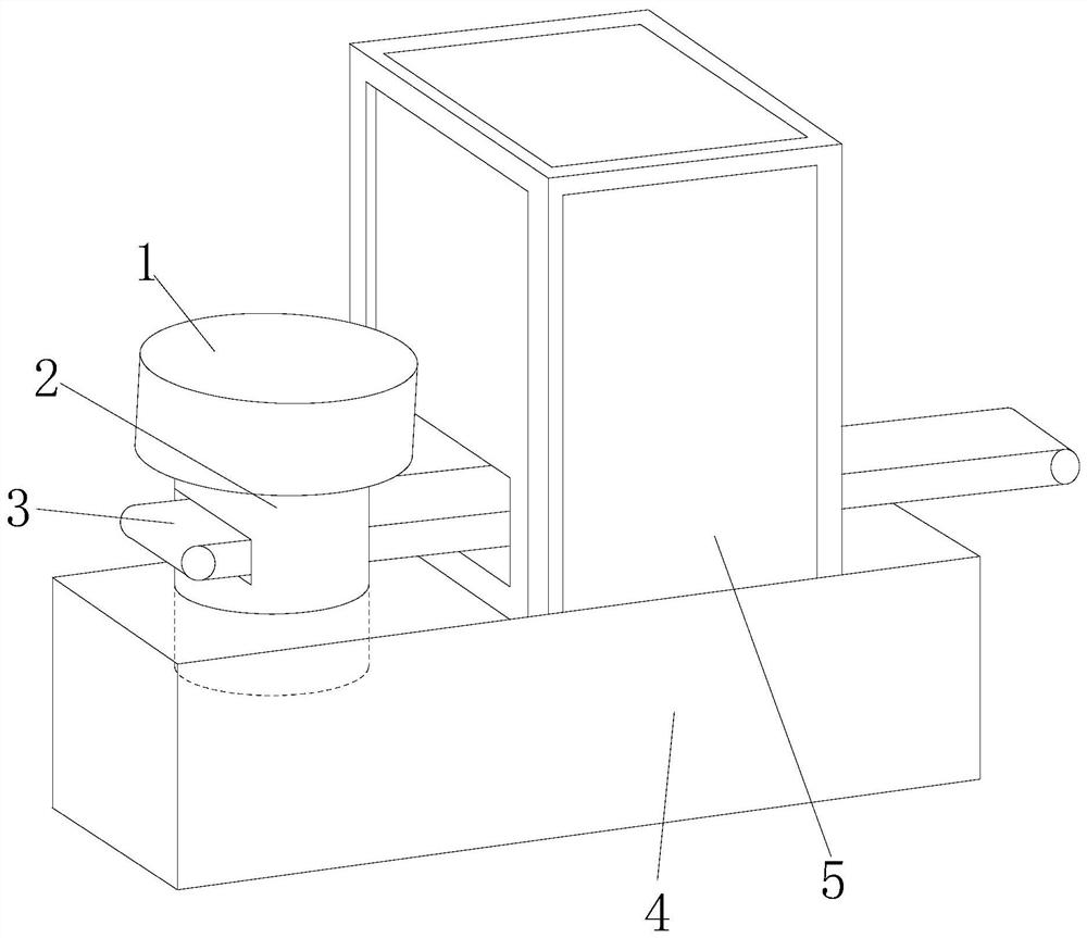
[0024] see Figure 1-Figure 6 , the present invention provides a display module bonding assembly line, the structure of which includes a fixed block 1, a cutting device 2, a conveyor belt 3, a fixed base 4, and an assembly cavity 5, the fixed block 1 is installed on the fixed base 4, the An assembly cavity 5 is provided on the fixed base 4, and the assembly cavity 5 is penetrated by the conveyor belt 3, and the conveyor belt 3 cooperates with the cutting device 2, and the cutting device 2 is installed in the fixed block 1;

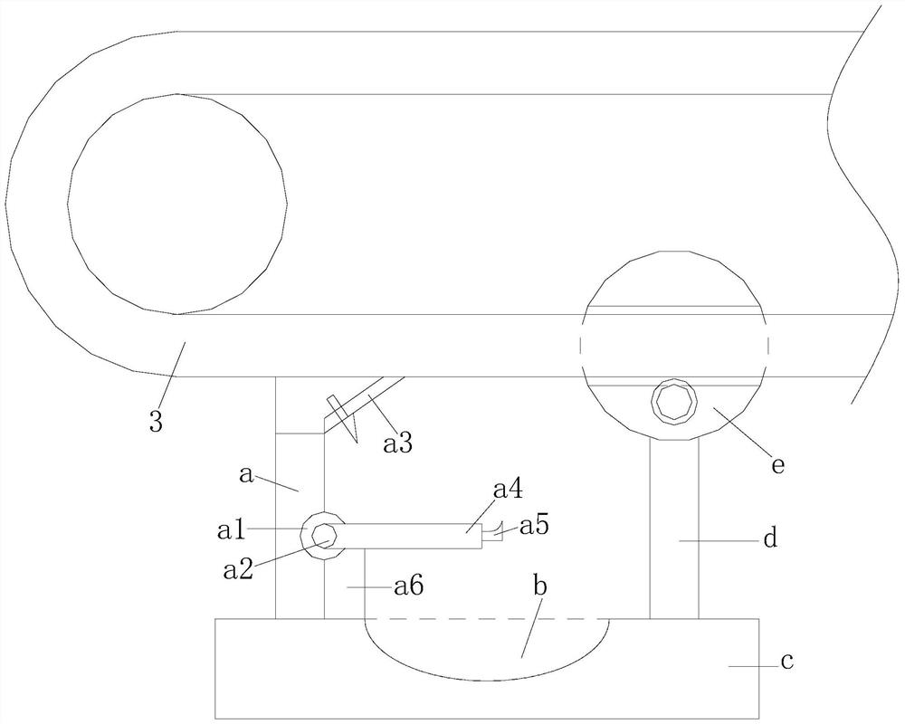
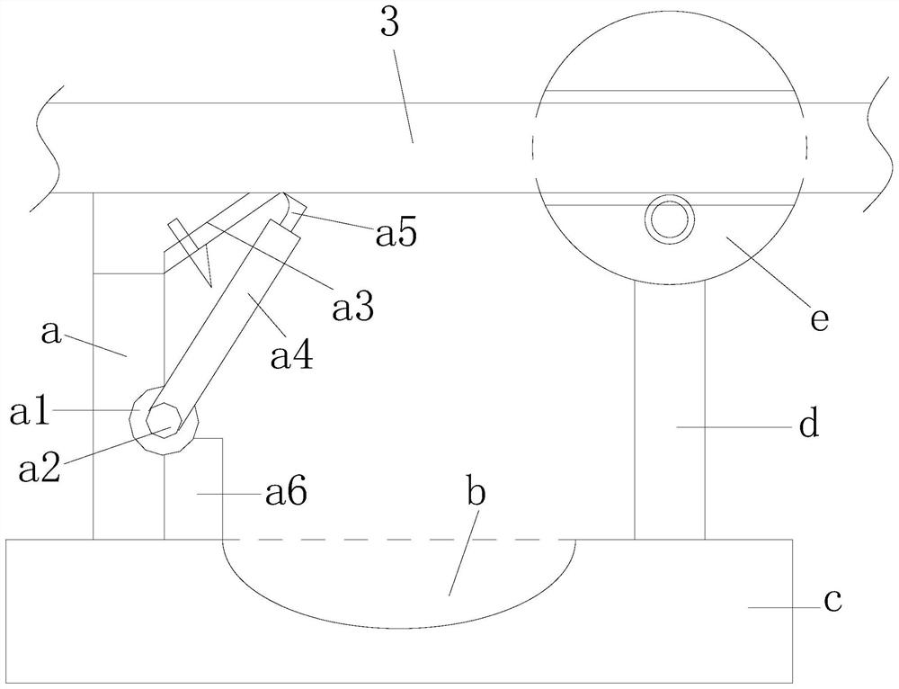
[0025] The cutting device 2 is composed of No. 1 column a, slag collection tank b, fixed seat c, No. 2 column d, and cleaning ball e. The No. 1 column a and No. 2 column d are set up in a symmetrical structure. The column a and the No. 2 column d are both fixed on the fixed seat c, and the fixed seat c is provided with a slag collection tank b, and the slag collection tank b is set up in a downward concave shape, and the slag collection tank b is embedded ...

Embodiment 2

[0032] see figure 1 , Figure 4-Figure 5 , the present invention provides a display module bonding assembly line, the structure of which includes a fixed block 1, a cutting device 2, a conveyor belt 3, a fixed base 4, and an assembly cavity 5, the fixed block 1 is installed on the fixed base 4, the The fixed base 4 is provided with an assembly cavity 5, the assembly cavity 5 is penetrated by the conveyor belt 3, the conveyor belt 3 is matched with the cutting device 2, and the cutting device 2 is installed in the fixed block 1; the cutting device 2 is composed of The first column a, the slag collection tank b, the fixed seat c, the second column d, and the cleaning ball e are composed of the first column a and the second column d in a symmetrical structure, and the first column a and the second column d are all fixed on the fixed seat c, the fixed seat c is provided with a slag collection tank b, the slag collection tank b is set up in a downward concave shape, and the slag ...


PUM


Abstract

The invention discloses an assembly line for bonding display screen modules. The structure includes a fixed block, a cutting device, a conveyor belt, a fixed base, and an assembly cavity. In cooperation, the cutting device is installed in the fixed block. The beneficial effect of the present invention is that the reverse movement of the roller and the conveyor belt is controlled by external mechanical force, so that the brush and the soft rod rub against the surface of the conveyor belt, and the impurities on the surface are cleaned. And because the brush and the soft rod are both tough materials, the brush and the soft rod will return to their original shape after they are separated from the surface of the conveyor belt. The combination of the fixed scraper and the movable scraper is used to remove the dried rubber from both sides to the middle, and the dropped rubber enters the slag collection tank to ensure that the flatness of the conveyor belt surface is not affected by impurities.

Description

technical field [0001] The invention relates to the field of assembly lines, in particular to a display screen module lamination assembly line. Background technique [0002] During the assembly process of the display module, dispensing of glue is required in the bonding process of the display. The traditional assembly method is completed manually, and the work efficiency is low. Therefore, the display module bonding assembly equipment has been developed to use the assembly line Assembled in the way that mechanization greatly improves the assembly efficiency, the current display module lamination assembly line has the following defects: [0003] The existing display module lamination assembly line is equipped with an automatic dispensing device, and the glue is automatically applied during the assembly process, which improves the assembly speed. If the amount of glue dispensed is small, the assembly of the display module will not be firm. Therefore, the amount of glue dispens...

Claims


Application Information

Patent Timeline
Patent Type & Authority Patents(China)
IPC IPC(8): B32B37/00B32B37/12B32B38/16
CPCB32B37/0053B32B37/1284B32B38/162
Inventor 李成镜
Owner 上海芯辉电子股份有限公司
Why Eureka
Try Eureka