Non-electric area detection and control method for rail transit vehicle

The technology of a rail transit vehicle and a control method is applied in the field of detection and control of a dead zone of a rail transit vehicle, and can solve problems such as a train falling into a dead zone

Active Publication Date: 2020-04-24
CRRC QINGDAO SIFANG ROLLING STOCK RES INST +1
View PDF6 Cites 4 Cited by
  • Summary
  • Abstract
  • Description
  • Claims
  • Application Information

AI Technical Summary

Problems solved by technology

[0004] The above two schemes still have certain limitations in practical application:
The limitation of forcing the low speed range threshold as the control condition of the bus contactor is: when the actual speed of the train is low, the train has the risk of falling into the dead zo

Method used


Image

  • Non-electric area detection and control method for rail transit vehicle
  • Non-electric area detection and control method for rail transit vehicle
  • Non-electric area detection and control method for rail transit vehicle

Examples


Embodiment 1

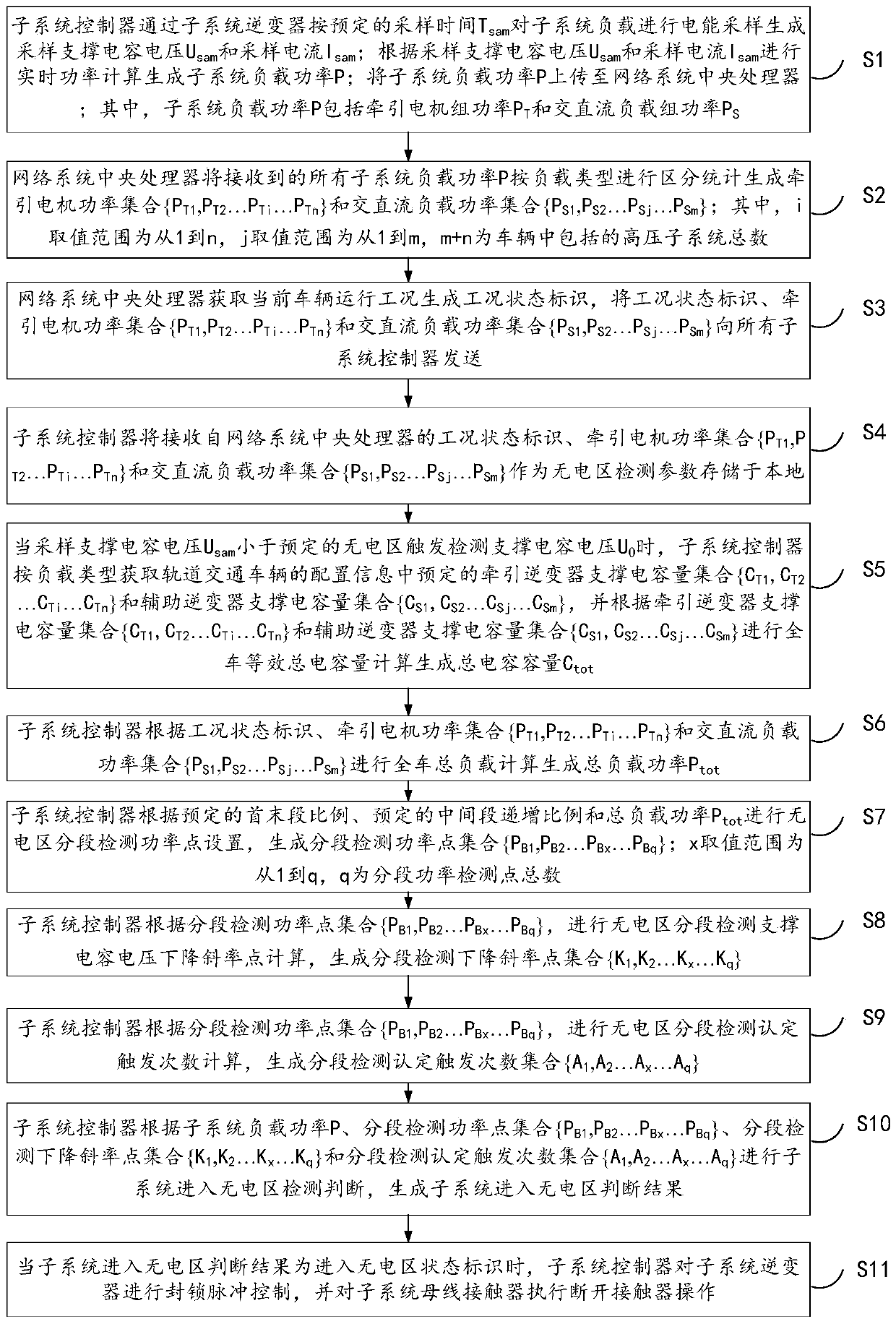
[0071] image 3 It is a schematic diagram of a method for detecting and controlling a non-electric zone of a rail transit vehicle provided in Embodiment 1 of the present invention, as shown in image 3 As shown, the non-electric zone detection and control method for rail transit vehicles in the embodiment of the present invention includes the following steps:

[0072] S1, the subsystem controller passes the subsystem inverter according to the predetermined sampling time T sam Sampling the electrical energy of the subsystem load to generate the sampling support capacitor voltage U sam and sampling current I sam ;According to the sampling support capacitor voltage U sam and sampling current I sam Perform real-time power calculation to generate subsystem load power P; upload subsystem load power P to the central processing unit of the network system;

[0073] Among them, the subsystem load power P includes the power of the traction motor unit P T and AC / DC load group power ...

Embodiment 2

[0147] Figure 5 It is a schematic diagram of a method for detecting and controlling a non-electric zone of a rail transit vehicle provided in Embodiment 2 of the present invention, as shown in Figure 5 As shown, the non-electric zone detection and control method for rail transit vehicles in the embodiment of the present invention includes the following steps:

[0148] S201, the subsystem controller determines the trigger detection support capacitor voltage U in the non-electric zone according to the system configuration and specifications of the rail transit vehicle 0 .

[0149] Here, according to the specific configuration and specifications of the actual vehicle, the U of each vehicle 0 may be different.

[0150] S202, the subsystem controller passes the subsystem inverter according to the preset sampling time T sam Sampling the electrical energy of the subsystem load to generate the sampling support capacitor voltage U sam and sampling current I sam ;According to th...


PUM


Abstract

The embodiment of the invention relates to a non-electric area detection and control method for a rail transit vehicle. The method comprises the steps of: generating subsystem load power through real-time power calculation; uploading the subsystem load power to a network system central processing unit; sending the working condition state identifier, the traction motor and the AC/DC load power setto all subsystem controllers by the network system central processing unit; when Usam is smaller than U0, calculating the total capacitance capacity by the subsystem controller; calculating the totalload power according to the working condition state identifier; generating a segmented detection power point set; generating segmented detection descending slope points according to the segmented detection power point set, and determining a trigger frequency set through segmented detection; judging whether to enter a power-free area or not according to the subsystem load power, the segmented detection power point, the segmented detection descending slope point and the segmented detection affirmation triggering frequency set; when it is judged that the system enters the power-free area, blocking subsystem inverter pulses, and executing contactor disconnection operation on a subsystem bus contactor.

Description

technical field [0001] The invention relates to the technical field of rail transit, in particular to a method for detecting and controlling a dead zone of a rail transit vehicle. Background technique [0002] There are two commonly used power supply methods for rail transit vehicles (subway, light rail, etc.): pantograph power supply and contact rail power supply. Among them, because the contact rail power supply method is low in cost and does not affect the urban style (ground line), it is more and more favored by emerging cities that develop rail transit. However, due to the limitations of objective factors such as some track crossing sections and turnout sections in the line, the power supply facilities will be interrupted, which will lead to the existence of power-free areas on the rail transit line. The longest part of the line in some non-electric areas is longer than the length between the two current receivers or pantographs that are farthest away from the entire v...

Claims


Application Information

Patent Timeline
IPC IPC(8): B60M3/02B60M3/06B60L3/00
CPCB60L3/0023B60L2200/26B60M3/02B60M3/06Y02T10/72
Inventor 邸峰马法运张佳波毕京斌王博曾凡飞王旭阳高瀚刘天宇
Owner CRRC QINGDAO SIFANG ROLLING STOCK RES INST
Why Eureka
Try Eureka