Eureka AIR delivers breakthrough ideas for toughest innovation challenges, trusted by R&D personnel around the world.

Optical nickel plating machine

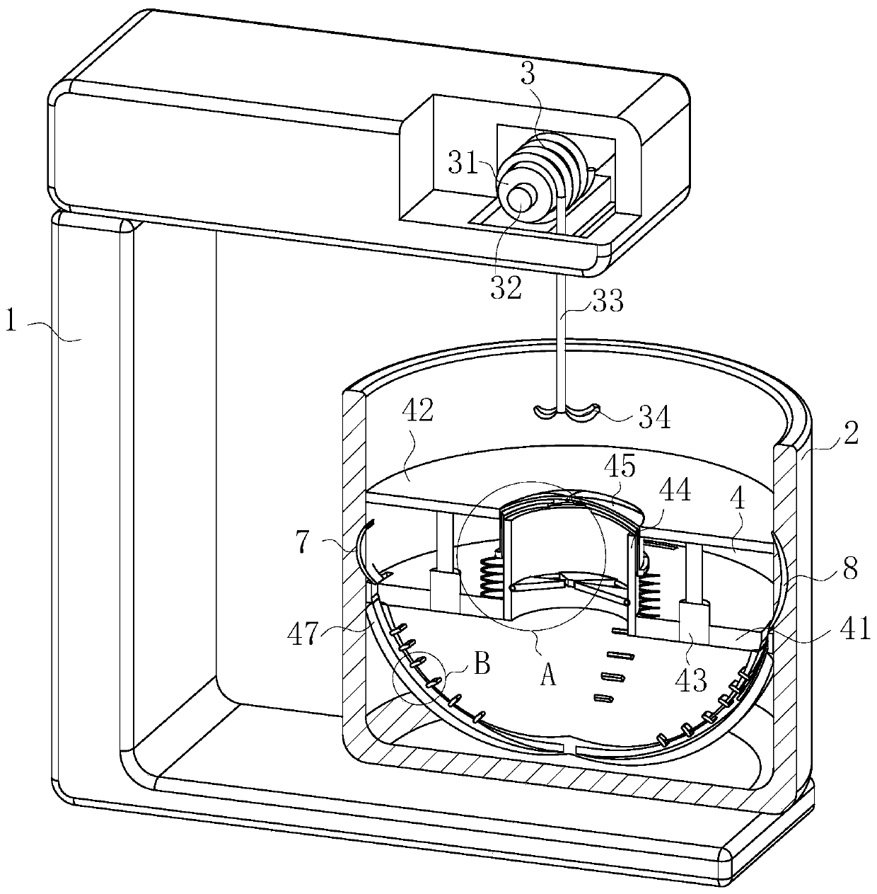
An optical plating and nickel plating technology, applied in liquid chemical plating, dryers, local stirring dryers, etc., can solve the problem of reducing the effect of nickel plating on small batches or small workpieces, affecting the efficiency of nickel plating, and large equipment. problem, to achieve the effect of increasing drying effect, simple structure and increasing utilization effect

Inactive Publication Date: 2020-04-24
戚英奎
View PDF0 Cites 0 Cited by
  • Summary
  • Abstract
  • Description
  • Claims
  • Application Information

AI Technical Summary

Problems solved by technology

[0004] In order to make up for the deficiencies in the prior art, the present invention proposes an optical nickel plating machine. The present invention is mainly used to solve the problem of the existing optical nickel plating device when performing nickel plating operations on small batches and complicated small parts. The structure of the existing nickel plating device is relatively complicated, and the equipment is relatively large. After the pretreatment of the workpiece is completed, the workpiece needs to be transferred to another nickel plating treatment device, which not only reduces the nickel plating effect of small batches or small workpieces, And lead to the waste of the solution before nickel plating and the solution during nickel plating, which in turn affects the high efficiency of nickel plating

Method used


Image

  • Optical nickel plating machine
  • Optical nickel plating machine
  • Optical nickel plating machine

Examples


Embodiment approach

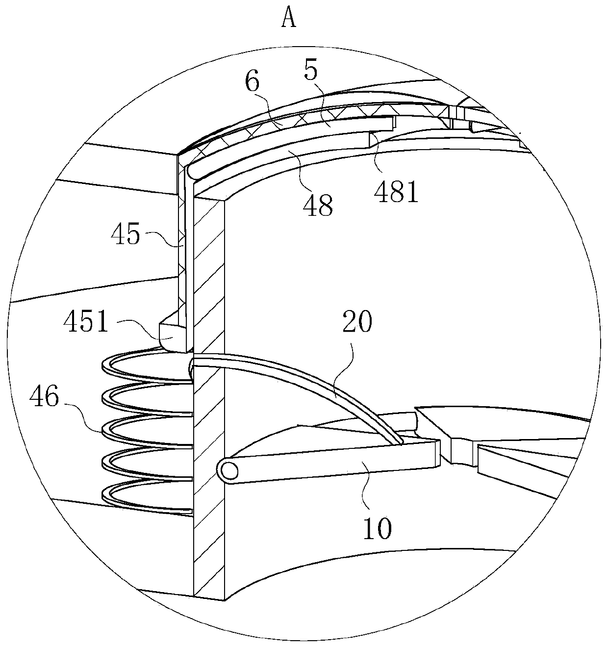
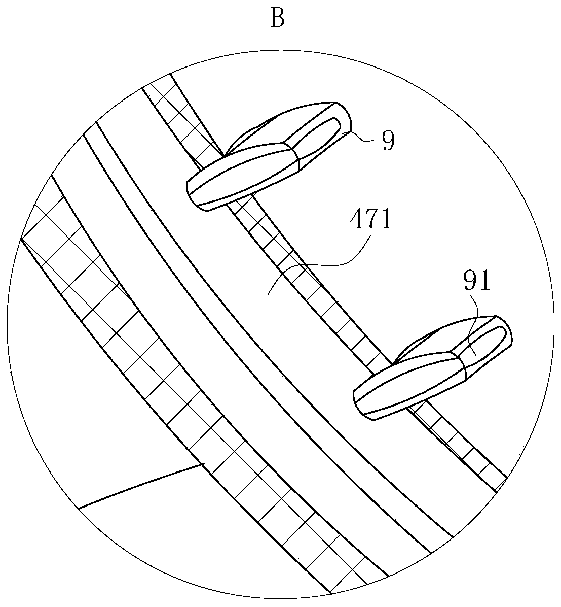
[0023] As an embodiment of the present invention, a plurality of T-shaped guide grooves 481 are opened on the arched guide plate 48, and the plurality of T-shaped guide grooves 481 correspond to the plurality of rubber sealing plates 45; The bottom end of the plate 45 is provided with a T-shaped rubber slide bar 5, and the T-shaped rubber slide bar 5 and the T-shaped guide groove are mutually slidingly arranged; When sliding, the T-shaped rubber slide bar 5 provided at the bottom of the rubber sealing plate 45 can slide down along the T-shaped guide groove, and then the T-shaped rubber slide bar 5 and the T-shaped guide groove slide and cooperate with each other, which can prevent the rubber seal plate from being When 45 slides downward or upward, the downward extrusion force of deflector 42 or the upward reaction force of limit spring 46 both act on the bottom end of rubber sealing plate 45, causing the top end of rubber sealing plate 45 to warp , thereby affecting the slidin...


PUM


Abstract

The invention belongs to the technical field of nickel plating equipment and specifically relates to an optical nickel plating machine. The optical nickel plating machine comprises a rack and a reaction tank. The reaction tank is mounted at the bottom end of the rack. A fixed plate is mounted in the reaction tank to divide the reaction tank into an acid pickling chamber and a nickel plating chamber. A flow guide plate is slidably mounted above the fixed plate through electric telescopic rods. A drying tube is fixed to the fixed plate. Hot steam is sprayed out from the drying tube. An arched guide plate is arranged above the drying tube. A plurality of rubber sealing plates are slidably arranged on the outer wall of the drying tube. The top ends of the rubber sealing plates define a sealingcavity at the top end of the arched guide plate. A nickel plating tank is arranged at the bottom end of the fixed plate and filled with nickel plating liquid. An electric heating wire is arranged inthe nickel plating tank. Through cooperation of a cleaning device, a drying device and the nickel plating tank, the occupied space of the optical nickel plating machine is reduced, and the optical nickel plating machine is simple in structure and fast and convenient to operate and facilitates nickel plating on small batches of small parts with complex appearance.

Description

technical field [0001] The invention belongs to the technical field of nickel plating equipment, in particular to an optical nickel plating machine. Background technique [0002] The nickel-plating equipment of prior art generally all comprises pretreatment and nickel-plating treatment two processes, if directly nickel-plating on workpiece without pre-treatment, the quality of nickel-plating is poor, easily produces phenomenons such as plated layer peeling off in flakes, white spots. Therefore, we generally need to pre-treat the workpiece to wash off the oxide film attached to the surface of the workpiece and the dirty grease on the oxide film. [0003] And existing optical nickel-plating device is when carrying out nickel-plating operation to small batches, and complex small parts, because existing nickel-plating device structure is more complicated, and equipment is relatively huge, needs to carry out pretreatment to workpiece after finishing. The workpiece is transferred...

Claims


Application Information

Patent Timeline
IPC IPC(8): C23C18/34C23C18/18C23C18/16C23G3/00F26B9/06F26B25/06
CPCC23C18/1601C23C18/1619C23C18/1827C23C18/34C23G3/00F26B9/06F26B25/06
Inventor 戚英奎周俊满卜东平
Owner 戚英奎
Why Eureka
Eureka Blog
Learn More