Stand column cantilever type yarn placement machine for chemical fiber spinning yarn

A cantilever type, oscillating wire machine technology, applied in fiber processing, textile and papermaking, artificial filament support, etc., can solve problems such as accidental drafting of silk threads, reduce production efficiency, and reduce product quality, and achieve uniform silk thread placement. order, improve production efficiency, and improve the effect of product quality

Pending Publication Date: 2020-04-24
晋中经纬技协机械有限公司
View PDF0 Cites 0 Cited by
  • Summary
  • Abstract
  • Description
  • Claims
  • Application Information

AI Technical Summary

Problems solved by technology

[0002] In the production process of chemical fiber spinning, it is necessary to arrange the spun yarns in a reasonable and orderly manner for drying in the next drying process. The existing spinning method is manual spinning. In the actual production process, manual swinging There are two deficiencies in the following two points: firstly, it needs 5-6 workers to work at the same time to meet the production requirements, the labor cost is high, and the labor intensity of the workers is high; The thickness is not uniform, which increases the drying time of the next drying process, increases the production cost, and reduces the production efficiency. In addition, manual spinning will cause the thread to be accidentally drawn, and in severe cases, the thread will be broken to form a defective product, reducing the production cost. Product quality increases the production cost of the product

Method used


Image

  • Stand column cantilever type yarn placement machine for chemical fiber spinning yarn
  • Stand column cantilever type yarn placement machine for chemical fiber spinning yarn
  • Stand column cantilever type yarn placement machine for chemical fiber spinning yarn

Examples


Embodiment Construction

[0010] The preferred embodiments of the present invention will be described in detail below in conjunction with the accompanying drawings, so that the advantages and features of the present invention can be more easily understood by those skilled in the art, so as to define the protection scope of the present invention more clearly.

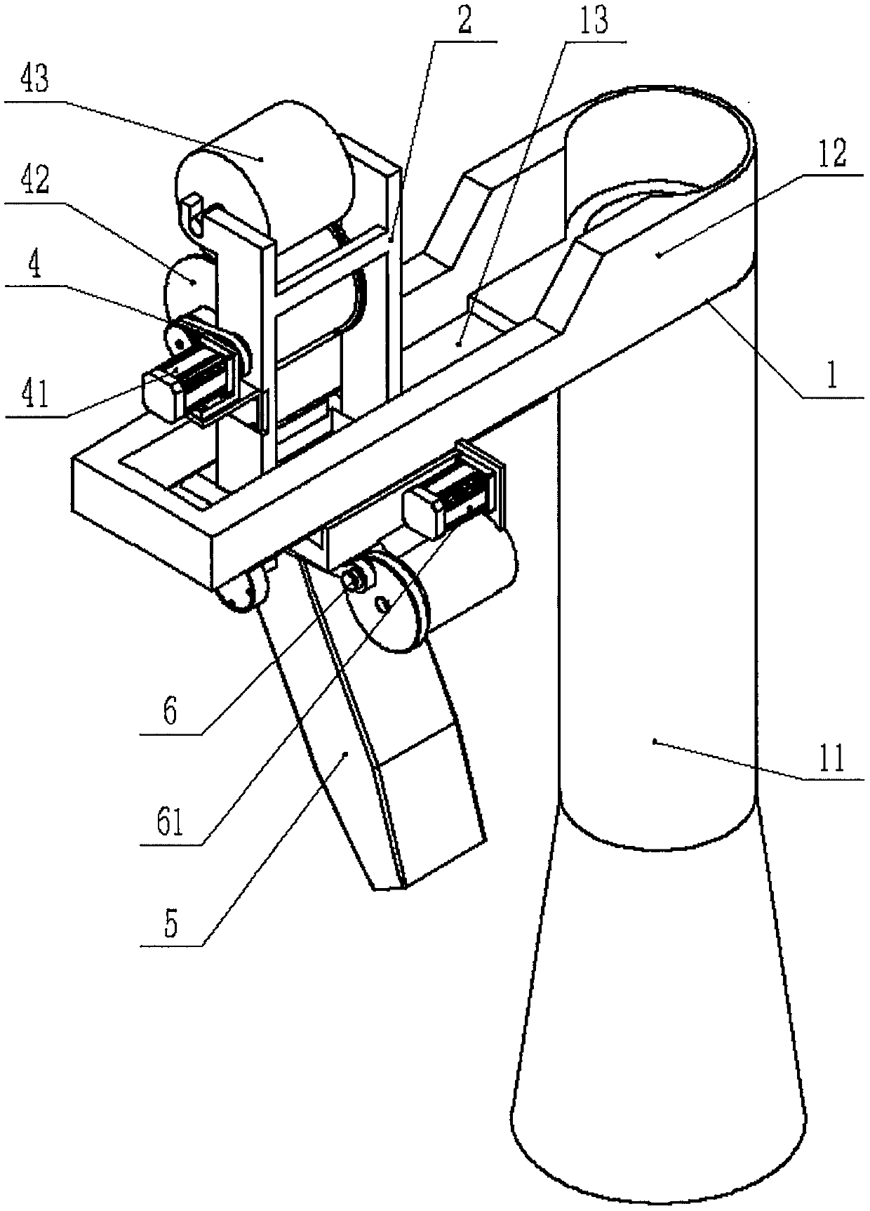
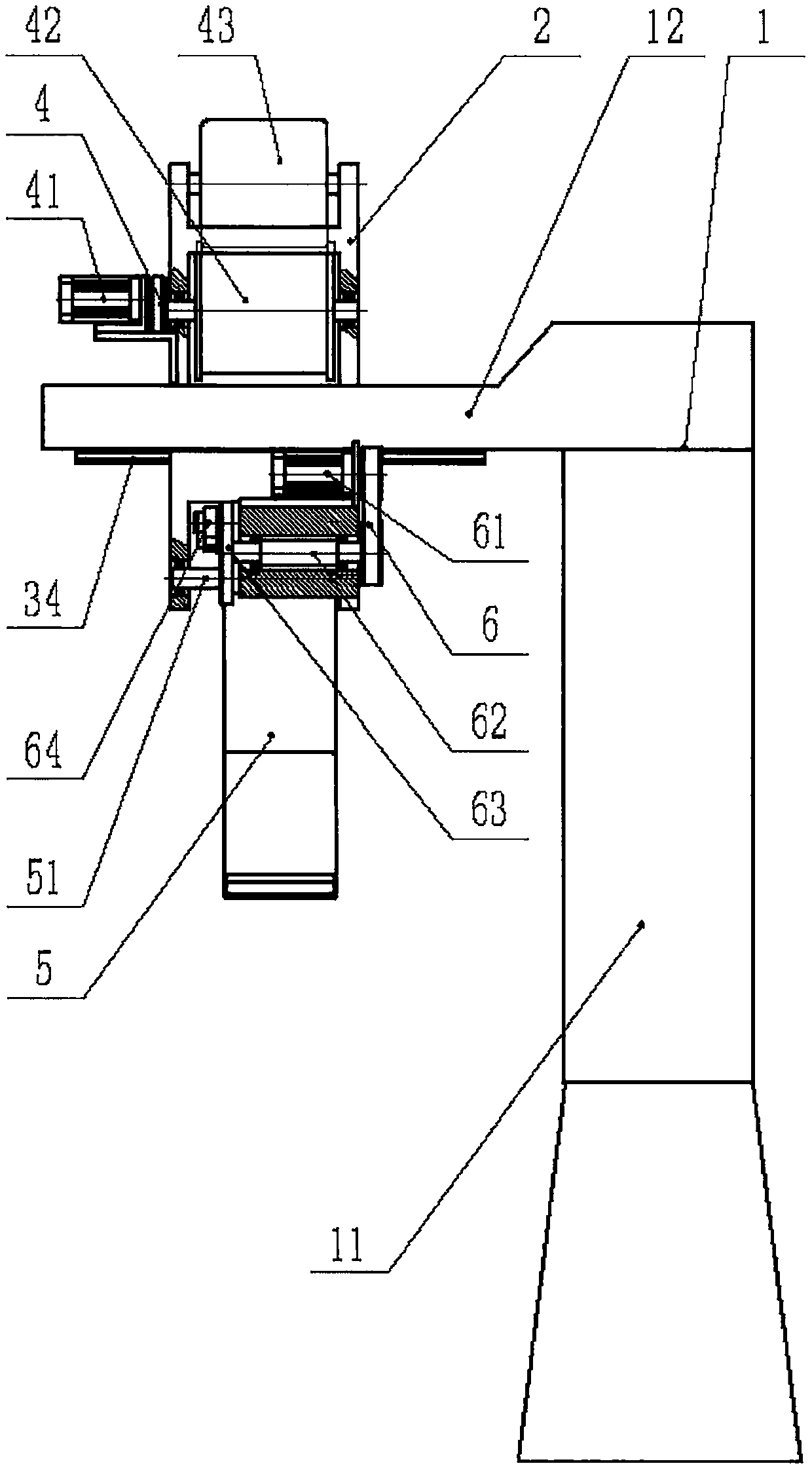
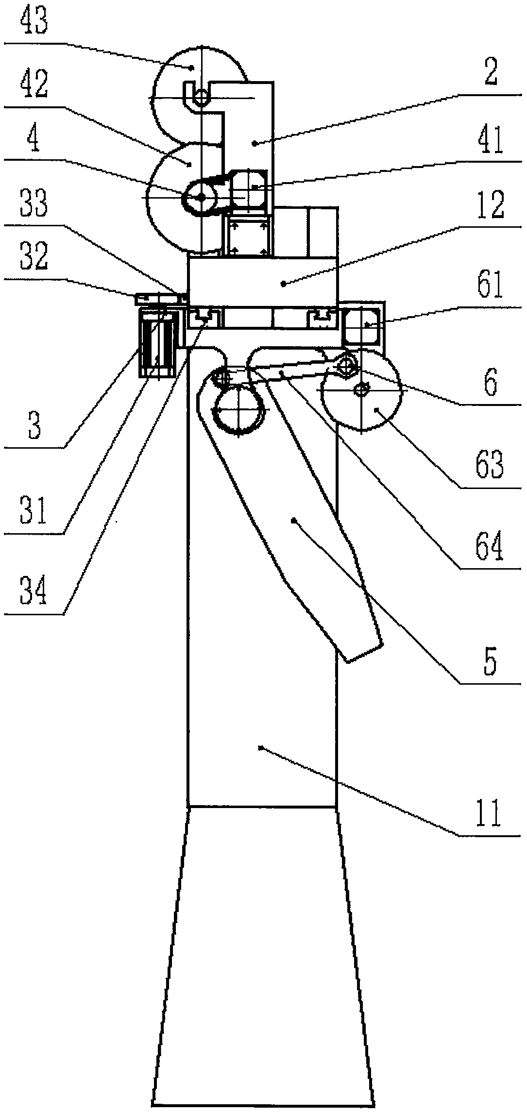
[0011] Such as figure 1 , figure 2 , image 3 with Figure 4 As shown, a column cantilever type spinning machine for chemical fiber spinning includes a fixed installation body 1, a sliding installation frame 2, a sliding device 3, a wire feeding device 4, a wire outlet swinging tube 5 and a swinging device 6. The appearance of the installation body 1 is in the shape of a "7", which includes a lower vertical column 11 and an upper horizontal cantilever 12. A long hole 13 is provided in the middle of the upper horizontal cantilever 12, and the sliding installation frame 2 is arranged in the long hole for installation. 13, it includes a connecti...


PUM


Abstract

The invention relates to a stand column cantilever type yarn placement machine for a chemical fiber spinning yarn. The stand column cantilever type yarn placement machine comprises a fixed mounting machine body (1), a sliding mounting machine body (2), a sliding device (3), a yarn feeding device (4), a yarn outlet swing tube (5) and a swing device (6); the fixed mounting machine body (1) comprisesa lower vertical column (11) and an upper transverse suspension arm (12); the sliding device (3) comprises a sliding driving motor (31), a gear (32), a rack (33) and a linear guide rail (34); the yarn feeding device (4) comprises a yarn feeding driving motor (41), a yarn feeding driving wheel (42) and a yarn feeding gravity driven wheel (43); and the swing device (6) comprises a swing driving motor (61), a middle transmission shaft (62), a crank disc (63) and a connecting rod (64). The stand column cantilever type yarn placement machine is novel and practical in function, and capable of realizing automatic and intelligent placement of the yarns, enabling the yarns to be placed uniformly in order, improving production efficiency and improving product quality.

Description

technical field [0001] The invention relates to a chemical fiber spinning equipment, in particular to a column cantilever swinging machine for chemical fiber spinning. Background technique [0002] In the production process of chemical fiber spinning, it is necessary to arrange the spun yarns in a reasonable and orderly manner for drying in the next drying process. The existing spinning method is manual spinning. In the actual production process, manual swinging There are two deficiencies in the following two points: firstly, it needs 5-6 workers to work at the same time to meet the production requirements, the labor cost is high, and the labor intensity of the workers is high; The thickness is not uniform, which increases the drying time of the next drying process, increases the production cost, and reduces the production efficiency. In addition, manual spinning will cause the thread to be accidentally drawn, and in severe cases, the thread will be broken to form a defectiv...

Claims


Application Information

Patent Timeline
IPC IPC(8): D01D10/06D01D10/04
CPCD01D10/0436D01D10/0481D01D10/06
Inventor 王琨艾铭晋
Owner 晋中经纬技协机械有限公司
Why Eureka
Try Eureka