Light roadbed structure of high-speed railway

A technology for high-speed railways and roadbeds, which can be used in infrastructure engineering, roads, bridge parts, etc., and can solve the problems of wide cross-sectional area, large reinforcement range of high-speed railway bases, mutual influence, etc., and achieves great engineering application prospects. , broad application space and promotion of application value, the effect of low cost

Pending Publication Date: 2020-04-24
CHINA RAILWAY DESIGN GRP CO LTD
View PDF0 Cites 2 Cited by
  • Summary
  • Abstract
  • Description
  • Claims
  • Application Information

AI Technical Summary

Problems solved by technology

[0002] Most of the traditional high-speed railway subgrades are constructed by subgrade filler compaction. The subgrade section is mostly a standard trapezoidal section. These unfavorable factors also restrict the further popularization and application of traditional subgrade structures in high-speed railway construction
Especially for the high-speed railway turnout area and the connecting line area, the traditional filling subgrade structure not only has a large subgrade section, but also has the problem of mutual influence of the additional settl...

Method used


Image

  • Light roadbed structure of high-speed railway

Examples


Embodiment 1

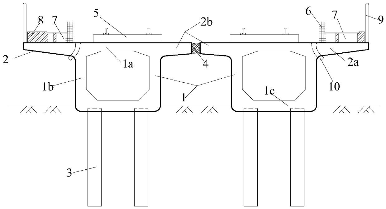
[0024] see figure 1 One embodiment of the present invention is shown, and the high-speed railway shown in the figure is a double-track high-speed railway. As shown in the figure, the light subgrade structures of the high-speed railway are arranged side by side along the extension direction of the high-speed railway, and each bears the load of the track and the train.

[0025] Each high-speed railway light subgrade structure includes a box-type subgrade 1 , a cantilever structure 2 and a rigid pile foundation 3 . Specifically, the box-shaped subgrade 1 includes: a horizontal top plate 1a, two vertical side wall plates 1b, and a horizontal bottom plate 1c formed integrally, each component is fixedly connected in turn to form a closed box-shaped structure, The outer contour of the section of the subgrade structure is a closed rectangle. The cantilever structure 2 is formed by extending outwards from the left and right ends of the top plate 1a of the box-shaped subgrade 1, where...

Embodiment 2

[0036] For the single-track high-speed railway, the high-speed railway light roadbed structure of the present invention includes a box-shaped roadbed 1, a cantilever structure 2 and a rigid pile foundation 3. The box-shaped subgrade 1 is fixedly connected by a horizontal top plate 1a, two vertical side wall plates 1b and a horizontal bottom plate 1c. The outer contour of its section is a closed rectangle; The cantilever structure 2 is formed by extension; the rigid pile foundation 3 is arranged at the bottom of the box-shaped subgrade 1, and is embedded and connected with the bottom plate 1c to play a supporting role. The cantilever structures 2 on both sides of the top plate 1a are symmetrically arranged, and the track plate and the track support system 5 are arranged in the middle of the top plate 1a. On the cantilever structure 2, anti-collision walls 6, cable troughs 7 and catenary column bases 8 are arranged in sequence from the inside to the outside. A protective fence 9...


PUM


Abstract

The invention discloses a light roadbed structure of a high-speed railway. The light roadbed structure comprises a box type roadbed, a cantilever structure and a rigid pile foundation, wherein the boxtype roadbed comprises a top plate which is integrally formed and horizontally arranged, two side wall plates which are vertically arranged and a bottom plate which is horizontally arranged, all thecomponents are fixedly connected to form a closed box-shaped structure, and the section of the closed box-shaped structure is in a closed rectangular shape; and the two ends of the top plate extend outwards to form outer cantilevers and extend towards the center line of the roadbed to form inner cantilevers, and damping rubber materials are filled between the adjacent inner cantilevers to seal andstop water. A track plate and a track supporting system are arranged on the top plate, an anti-collision wall, a cable trough and a contact net stand column base are sequentially arranged on the outer cantilevers, and a protective fence is arranged at the ends of the outer cantilevers. Vertical drainage ducts are formed in the positions, close to the outer side wall plates, of the top plate of the box type roadbed; a rigid pile foundation is arranged at the bottom of the box type roadbed. According to the method, the sloping range of the slope of the high-speed railway embankment is greatly reduced, the foundation reinforcement work amount is reduced, and the use amount of rigid piles and the filling amount of railway roadbed filler are reduced.

Description

technical field [0001] The invention belongs to the technical field of railway engineering, in particular to a light roadbed structure for high-speed railways. Background technique [0002] Most of the traditional high-speed railway subgrades are constructed by subgrade filler compaction. The subgrade section is mostly a standard trapezoidal section. These unfavorable factors also restrict the further popularization and application of traditional subgrade structures in high-speed railway construction. Especially for the high-speed railway turnout area and the connection line area, the use of traditional earth-filled subgrade structure not only has a large subgrade section, but also has the problem of mutual influence between the additional settlement deformation of the two subgrades. In order to reduce the land occupation of the traditional trapezoidal section subgrade structure and control the self-weight of the basic road structure, the retaining wall structure has been p...

Claims


Application Information

Patent Timeline
IPC IPC(8): E01B1/00E01B2/00E01D2/04E01D19/10E02D27/16E01D101/26
CPCE01B1/002E01B1/008E01B2/006E01B2204/09E01D2/04E01D19/10E01D19/103E01D2101/26E02D27/16
Inventor 宋绪国郭帅杰陈洪运肖世伟王铸
Owner CHINA RAILWAY DESIGN GRP CO LTD
Why Eureka
Try Eureka