Installation structure of fabricated ceiling heat insulation system
A heat insulation and installation structure technology, applied in the direction of insulation, ceiling, building components, etc., can solve the problems of super high installation difficulty, super large space top surface deformation, seam closure warping and other problems, and achieve the solution of super high installation difficulty, The effect of enhancing the effect
- Summary
- Abstract
- Description
- Claims
- Application Information
AI Technical Summary
Problems solved by technology
Method used
Image

Examples
Embodiment 1
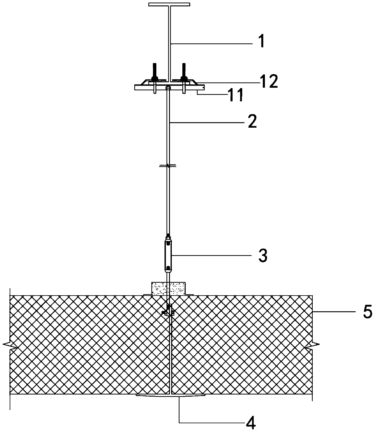
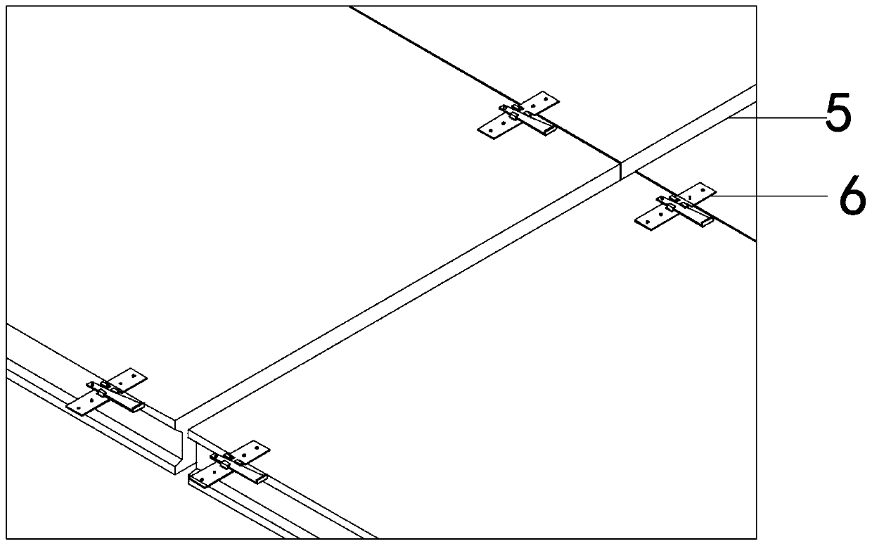
[0025] See Figure 1 to Figure 3 , The figure shows the installation structure of a prefabricated ceiling thermal insulation system in an embodiment of the present invention, which is mainly provided with a first connecting piece 11 fixed on the steel truss secondary beam 1, and two of the first connecting piece 11 Each end is provided with at least one fixing member 12, the first connecting member 11 is connected to the steel structure truss secondary beam 1 through the fixing member 12, the bottom of the first connecting member 11 is connected with a boom 2, and the opposite end of the boom 2 is fixedly connected There is a second connecting piece 3, a hanging beam 4 is connected to the second connecting piece 3, a ceiling plate 5 is connected to the other end of the hanging beam 4, and at least one locking member 6 is arranged between adjacent ceiling plates 5, the locking member 6 includes a first locking plate 61, a second locking plate 62 and a clamping plate 63. The first...
Embodiment 2
[0039] See Figure 5 , The figure shows the installation structure of a prefabricated ceiling thermal insulation system provided by the second embodiment of the present invention. This embodiment further makes the following as an improved technical solution on the basis of the foregoing embodiments: The ceiling board 5 is a metal-faced rock wool composite board. The metal-faced rock wool composite board includes a double-sided metal plate 51 and an insulating rock wool 52. The insulating rock wool 52 is filled in the double-sided metal plate 51, and the double-sided metal plate 51 and the insulating rock A PE coating is provided between the cotton 52. The specific metal surface rock wool composite board specification is 8000mm*1130mm*240mm, the thickness of the double-sided metal plate: 0.6mm, AZ100g / ㎡; PE coating. The double-sided metal plate is filled with thermal insulation rock wool (composed of Shandong Taishi and hydrophobic rock wool), density: 120Kg / m 3 . The thermal c...
Embodiment 3
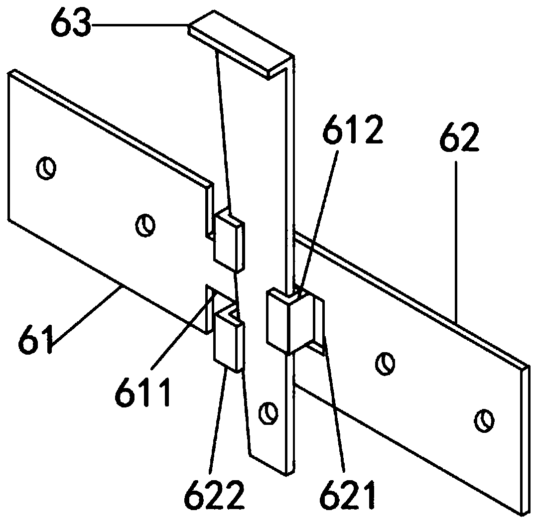
[0041] See Figure 1 to Figure 4 , The figure shows the installation structure of a prefabricated ceiling thermal insulation system provided by the third embodiment of the present invention. This embodiment further makes the following as an improved technical solution on the basis of the foregoing embodiments: A first connecting plate 611 extends from the end of the first locking plate 61, a first hook 612 is connected to the first connecting plate, and a groove 621 matching the first connecting plate 611 is provided on the second locking plate 62. Two second hooks 622 are connected to the second locking plate 62. The card slot 621 is located between the two second hooks 622. The card plate 63 is an L-shaped card plate. The first hook 612 and the second hook 622 are locked. Hold the card board 63. Through the arrangement of the above structure, the suspended ceiling can be made straight and smooth, without warping or deformation, so as to achieve the purpose of improving the i...
PUM
| Property | Measurement | Unit |
|---|---|---|
| Thickness | aaaaa | aaaaa |
| Density | aaaaa | aaaaa |
Abstract
Description
Claims
Application Information
 - R&D
- Intellectual Property
- Life Sciences
- Materials
- Tech Scout
- Unparalleled Data Quality
- Higher Quality Content
- 60% Fewer Hallucinations
Browse by: Latest US Patents, China's latest patents, Technical Efficacy Thesaurus, Application Domain, Technology Topic, Popular Technical Reports.
© 2025 PatSnap. All rights reserved.Legal|Privacy policy|Modern Slavery Act Transparency Statement|Sitemap|About US| Contact US: help@patsnap.com