Supercharge Your Innovation With Domain-Expert AI Agents!

Construction method of large steel formwork cast-in-place column for column steel bars adopting binding and overlapping manner

A construction method and technology of cast-in-place columns, which are applied in the direction of formwork/formwork/work frame, columns, pier columns, etc., can solve the problems of high labor consumption, troublesome construction, poor appearance quality, etc., and achieve reduced construction costs and improved construction efficiency. Efficiency and process reduction effects

Inactive Publication Date: 2020-04-24
宁波优造建筑科技有限公司
View PDF13 Cites 3 Cited by
  • Summary
  • Abstract
  • Description
  • Claims
  • Application Information

AI Technical Summary

Problems solved by technology

[0002] In the construction of traditional cast-in-place reinforced concrete columns, the operation scaffolding is usually erected first, and then the column steel bars are vertically tied. When the height of the column is large, the erection of the scaffolding and the binding of the steel bars are labor-intensive and have high safety risks. Wooden formwork and hoops are used, and the column section is large. Sometimes it is necessary to set up pull bolts, the construction is troublesome, the cost is high, and the appearance quality is poor, so it is difficult to meet the requirements of fair-faced concrete.
The inventor’s previous published patent (201711188594.3) provided a construction method for cast-in-place columns with large steel molds. This method is simple and quick to operate when the main reinforcement is long. Binding and lapping of steel bars lead to the failure of installation and construction of the overall large steel formwork. An efficient construction method has not been reported for the independent closing of the lower large steel formwork and the overall hoisting of the upper large steel formwork.

Method used


Image

  • Construction method of large steel formwork cast-in-place column for column steel bars adopting binding and overlapping manner
  • Construction method of large steel formwork cast-in-place column for column steel bars adopting binding and overlapping manner
  • Construction method of large steel formwork cast-in-place column for column steel bars adopting binding and overlapping manner

Examples


Embodiment Construction

[0025] In order to facilitate the understanding of the present invention, the present invention will be described more fully below with reference to the associated drawings. Preferred embodiments of the invention are shown in the accompanying drawings. However, the present invention can be embodied in many different forms and is not limited to the embodiments described herein. On the contrary, the purpose of providing these embodiments is to make the disclosure of the present invention more thorough and comprehensive.

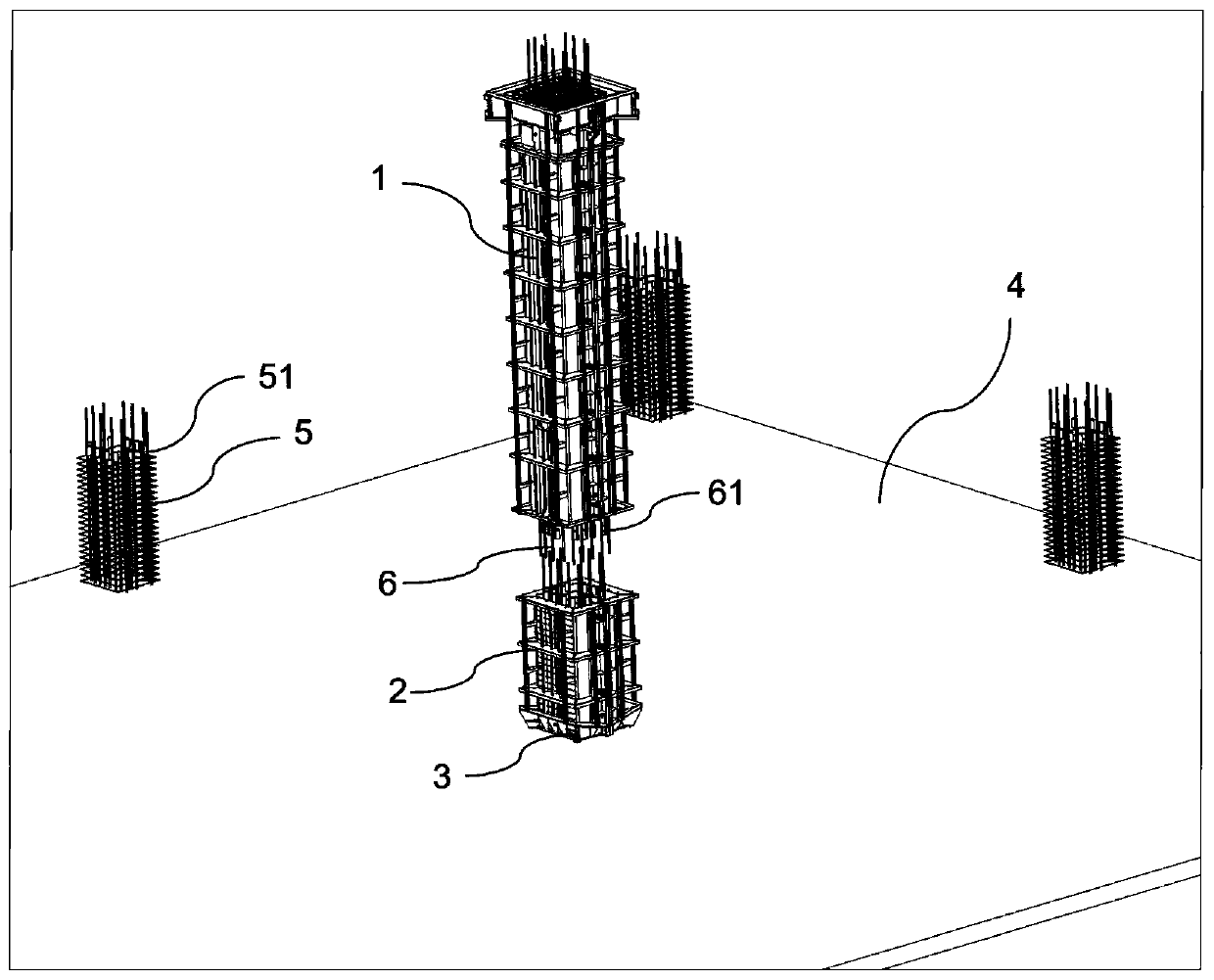
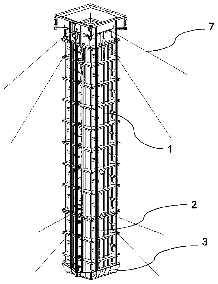
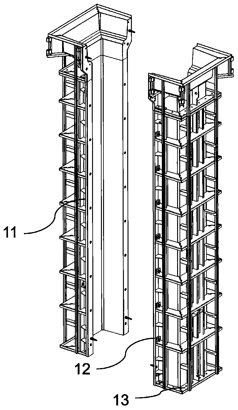
[0026] see Figure 1 to Figure 4 , in the embodiment of a large steel mold cast-in-place column construction method in which the column reinforcement adopts a binding and lapping method provided by the present invention, the upper large steel mold 1 with a column cap, the lower large steel mold 2, and the footing The steel mold 3 and the base 4 are characterized in that the column reinforcement adopts the large steel mold cast-in-place column of the binding a...


PUM


Abstract

The invention discloses a construction method of large steel formwork cast-in-place column for column steel bars adopting a binding and overlapping manner. The construction method comprises an upper large steel formwork with a column cap, a lower large steel formwork, a bottom foot steel formwork and a base. According to the construction method, splicing type cast-in-place large steel formwork with independent closing of the large steel formwork under column and integral lifting of the large steel formwork over column, and the construction problem when the column steel bars are bound and overlapped is solved; and the assembly and disassembly are convenient, the concrete appearance quality is good, the operation scaffold for binding steel bars and formwork is omitted, the procedure is reduced, rapid hoisting is achieved, and the construction efficiency of the large steel formwork is improved.

Description

technical field [0001] The invention relates to the field of building construction, in particular to a column construction method. Background technique [0002] In the construction of traditional cast-in-place reinforced concrete columns, the operation scaffolding is usually erected first, and then the column steel bars are vertically tied. When the height of the column is large, the erection of the scaffolding and the binding of the steel bars are labor-intensive and have high safety risks. Wooden formwork and hoops are used, and the column section is large. Sometimes it is necessary to set up pull bolts, the construction is troublesome, the cost is high, and the appearance quality is poor, so it is difficult to meet the requirements of fair-faced concrete. The inventor’s previous published patent (201711188594.3) provided a construction method for cast-in-place columns with large steel molds. This method is simple and quick to operate when the main reinforcement is long. ...

Claims


Application Information

Patent Timeline
Patent Type & Authority Applications(China)
IPC IPC(8): E04G13/02E04C3/34
CPCE04C3/34E04G13/02
Inventor 许佳伟王瑞杨峰
Owner 宁波优造建筑科技有限公司
Features
  • R&D
  • Intellectual Property
  • Life Sciences
  • Materials
  • Tech Scout
  • Unparalleled Data Quality
  • Higher Quality Content
  • 60% Fewer Hallucinations
Learn More