Ultimate load reduction method of yaw bearing based on nacelle attitude for wind turbines

A technology for wind turbines and extreme loads, which is applied in the control of wind turbines, wind turbines, wind power generation, etc., to achieve stable load reduction effects, low hardware costs, and safe operation

Active Publication Date: 2020-11-03
GUANGDONG MINGYANG WIND POWER IND GRP CO LTD
View PDF6 Cites 0 Cited by
  • Summary
  • Abstract
  • Description
  • Claims
  • Application Information

AI Technical Summary

Problems solved by technology

The blades are lengthened and the diameter of the wind rotor is enlarged. The benefit is that the sweeping area is larger and more wind energy can be captured; but the disadvantage is that it brings greater ultimate loads, including hub loads, yaw loads, and tower loads. frame load

Method used


Image

  • Ultimate load reduction method of yaw bearing based on nacelle attitude for wind turbines
  • Ultimate load reduction method of yaw bearing based on nacelle attitude for wind turbines
  • Ultimate load reduction method of yaw bearing based on nacelle attitude for wind turbines

Examples


Embodiment Construction

[0033] The present invention will be further described below in conjunction with specific examples.

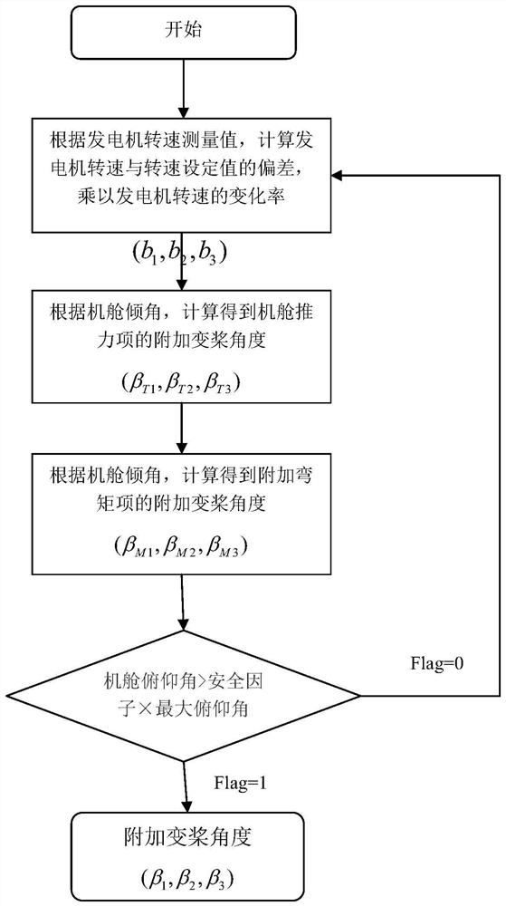
[0034] The wind turbine generator set provided in this embodiment is based on the nacelle attitude yaw bearing limit load reduction method, including the following steps:

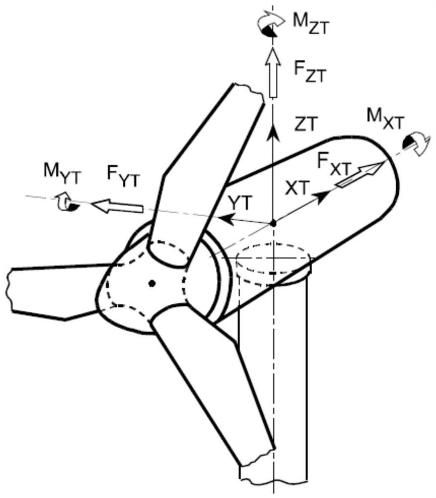
[0035] 1) An inclination sensor needs to be installed in the cabin, which is used to measure the pitch angle of the cabin. In the cabin coordinate system (see figure 1 ), the positive direction of the pitch angle is defined as M YT The direction of rotation, that is, according to the right-hand rule, thumb and M YT parallel and pointing to M YT In the forward direction, the direction angle pointed by the four-finger bend is the pitch angle, use θ d express.

[0036] It is best to use a high-precision inclination sensor based on capacitive 3D-MEMS technology for inclination measurement. This sensor can resist the interference of external acceleration, and it must also have excellent reliability and extr...


PUM


Abstract

The invention discloses a method for yaw bearing limit load reduction of a wind turbine generator system based on the posture of a cabin. The method is based on the posture of the cabin measured by aninclination angle sensor. When the extreme gust wind condition occurs, through the cabin posture change sensed by the inclination angle sensor in the cabin, load reduction control is applied, the yawbearing limit load of the wind turbine generator system under the extreme working condition is reduced, and therefore the safe operation of the wind turbine generator system is guaranteed. Accordingto the method, the limit load of a yaw bearing can be effectively reduced, the load reduction effect is stable and reliable, the application range is wide, the hardware cost is low, and great advantages are brought to the whole machine design, type selection, manufacture and operation of the wind turbine generator system.

Description

technical field [0001] The present invention relates to the technical field of wind power generation, in particular to a method for reducing the ultimate load of a yaw bearing based on the attitude of a nacelle for a wind power generating set. Background technique [0002] With the continuous development of onshore wind power, high-quality wind resources are becoming less and less, and the average wind speed is gradually decreasing. In order to capture more wind energy, wind turbines are gradually developing towards large megawatts and large wind rotor diameters. The blades are lengthened and the diameter of the wind rotor is enlarged. The benefit is that the sweeping area is larger and more wind energy can be captured; but the disadvantage is that it brings greater ultimate loads, including hub loads, yaw loads, and tower loads. rack load. For the whole machine, the ultimate load of the yaw bearing becomes one of the biggest bottlenecks in its design and manufacture. Acc...

Claims


Application Information

Patent Timeline
Patent Type & Authority Patents(China)
IPC IPC(8): F03D7/04
CPCF03D7/0224F03D7/042F05B2270/327Y02E10/72Y02P70/50
Inventor 李刚马冲黄国燕
Owner GUANGDONG MINGYANG WIND POWER IND GRP CO LTD
Why Eureka
Try Eureka