Film antenna and display device including the same

An antenna device and electrode wire technology, applied in the field of display devices, can solve problems such as image degradation and inability to provide solutions

Active Publication Date: 2020-04-24
DONGWOO FINE CHEM CO LTD
View PDF17 Cites 0 Cited by
  • Summary
  • Abstract
  • Description
  • Claims
  • Application Information

AI Technical Summary

Problems solved by technology

[0007] For example, Korean Published Patent Application No. 2013-0095451 discloses an antenna integrated into a display panel, however, cannot provide a solution to image degradation caused by the antenna

Method used


Image

  • Film antenna and display device including the same
  • Film antenna and display device including the same
  • Film antenna and display device including the same

Examples


experiment example 1

[0124] Experimental Example 1: Evaluating the Visibility of Electrodes Based on the Visibility Index

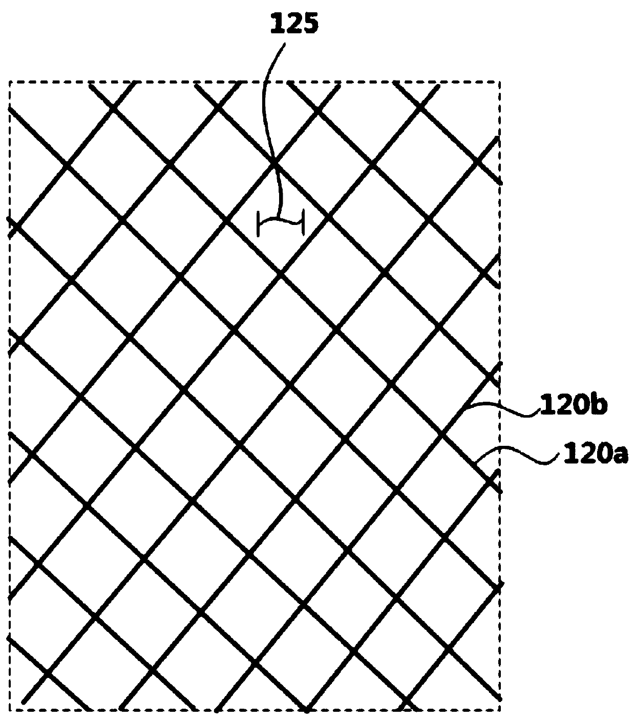
[0125] Formed on the dielectric layer using an alloy of silver, palladium and copper (APC) image 3 The network structure shown. The line width of the electrode line is 3 μm, and the thickness (or height) of the electrode line is Control the length of the diagonal in the X direction (denoted as X in Table 1) and the length of the diagonal in the Y direction (denoted as Y in Table 1) in the rhombus cell to change the minimum length of the opposite side ( Denoted as A) in Table 1, antenna samples of Examples and Comparative Examples were prepared.

[0126] The contrast of the samples was obtained from images measured using an Olympus microscope SZ61. The distance between the microscope and the sample, defined as the vertical distance between the tip of the objective lens and the electrode, was 40 cm. The contrast ratio was calculated by the following equation using the l...

experiment example 2

[0143] Experimental Example 2: Evaluation of Resistance and Signal Loss Based on the Line Width of Electrode Lines

[0144] Formed on dielectric layer using APC alloy image 3 The network structure shown. As prepared in Examples 1-6 of Experimental Example 1, the minimum distance between the opposite sides of the diamond-shaped cells was fixed at 196 μm, and the line width of the electrode lines was changed to prepare samples.

[0145] The signal loss (S21, dB), linear resistance and transmittance of the samples were measured.

[0146] Specifically, the signal loss was measured from S-parameters obtained by a network analyzer at 28 GHz. Linear resistance was measured by resistance simulation (Q3D tools) method. The transmittance was measured by the same method as that of Experimental Example 1. The results are shown in Table 3 below.

[0147] [table 3]

[0148] Line Width (μm) Signal loss (S21,dB) Linear resistance (Ω) Transmittance sample 1 0.5...


PUM

PropertyMeasurementUnit
widthaaaaaaaaaa
widthaaaaaaaaaa
widthaaaaaaaaaa

Abstract

According to embodiments of the present invention, provided is a film antenna which comprises: a dielectric layer; and a radiation electrode disposed on an upper surface of the dielectric layer and including a plurality of electrode lines. The radiation electrode exhibits a visibility index in the range of -1.4 to 1.9. By designing the radiation electrode, the electrode visibility can be suppressed and the signal sensitivity can be increased.

Description

[0001] Cross References and Priority Claims to Related Applications [0002] This application claims priority from Korean Patent Application No. 10-2018-0123058 filed with the Korean Intellectual Property Office (KIPO) on October 16, 2018, the entire disclosure of which is incorporated herein by reference. technical field [0003] The present invention relates to an antenna device and a display device including the same. More particularly, the present invention relates to an antenna device including an electrode pattern and a display device including the antenna device. Background technique [0004] With the development of information technology, wireless communication technologies such as Wi-Fi, Bluetooth, etc. are combined with display devices such as in smart phones. In this case, the antenna can be combined with the display device to provide a communication function. [0005] Mobile communication technology has been rapidly developed, and antennas capable of UHF commun...

Claims


Application Information

Patent Timeline
Patent Type & Authority Applications(China)
IPC IPC(8): H01Q1/38H01Q1/50H01Q1/22G09F9/00
CPCH01Q1/38H01Q1/50H01Q1/22G09F9/00H04M1/026H01Q1/364H01Q9/0407H01Q1/243H01Q1/422H01Q1/40H04M1/0266
Inventor 柳汉燮安基焕朴东必白成颢
Owner DONGWOO FINE CHEM CO LTD
Why Eureka
Try Eureka