Mechanical device

A technology of mechanical devices and components, applied in the field of tie rod fertilization machinery, can solve the problems of complex device structure, low automation, inability to adjust the discharge speed, etc., and achieve the effects of improving fertilization efficiency, high degree of automation, and increased convenience.

Inactive Publication Date: 2020-04-28
JIASHAN LUOJIA FURNITURE CO LTD
View PDF1 Cites 3 Cited by
  • Summary
  • Abstract
  • Description
  • Claims
  • Application Information

AI Technical Summary

Problems solved by technology

[0003] The Chinese patent discloses a mechanical device (authorized notification number CN207135460U). This patented technology is a forming single tie rod type fertilizing mechanical device, which can be formed into a combined fertilizing mechanical device. However, most of the mechanical devices on the market cannot place multiple fertilizers at the same time. Selective fertilization is less convenient to use, and the discharge speed cannot be adjusted quickly and conveniently, which is not conducive to the adjustment of fertilization amount. In order to manually adjust the discharge speed, it is inconvenient to use, and the automation is low. Most of the devices have complex structures, which is not conducive to the operation and maintenance of the devices. Most of the devices are large in size, which is not conducive to convenient fertilization on different lands.
It solves the problem that multiple fertilizers cannot be placed at the same time, and solves the problem of manual adjustment of the output speed, which is inconvenient to adjust

Method used


Image

  • Mechanical device
  • Mechanical device
  • Mechanical device

Examples


Embodiment Construction

[0025] The following will clearly and completely describe the technical solutions in the embodiments of the present invention with reference to the accompanying drawings in the embodiments of the present invention. Obviously, the described embodiments are only some, not all, embodiments of the present invention. Based on the embodiments of the present invention, all other embodiments obtained by persons of ordinary skill in the art without making creative efforts belong to the protection scope of the present invention.

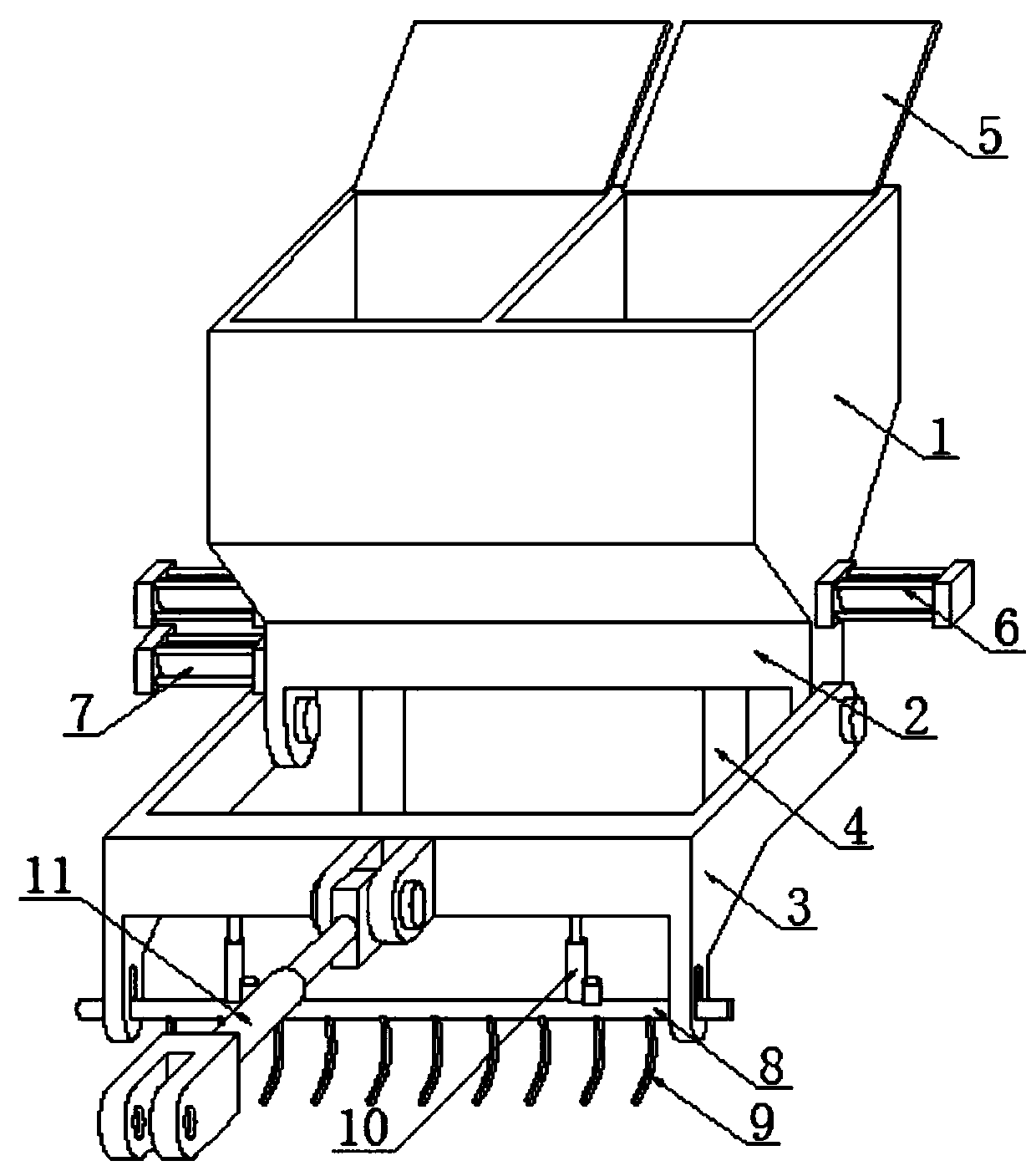
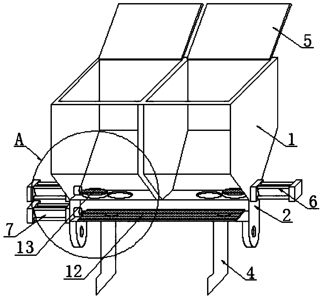
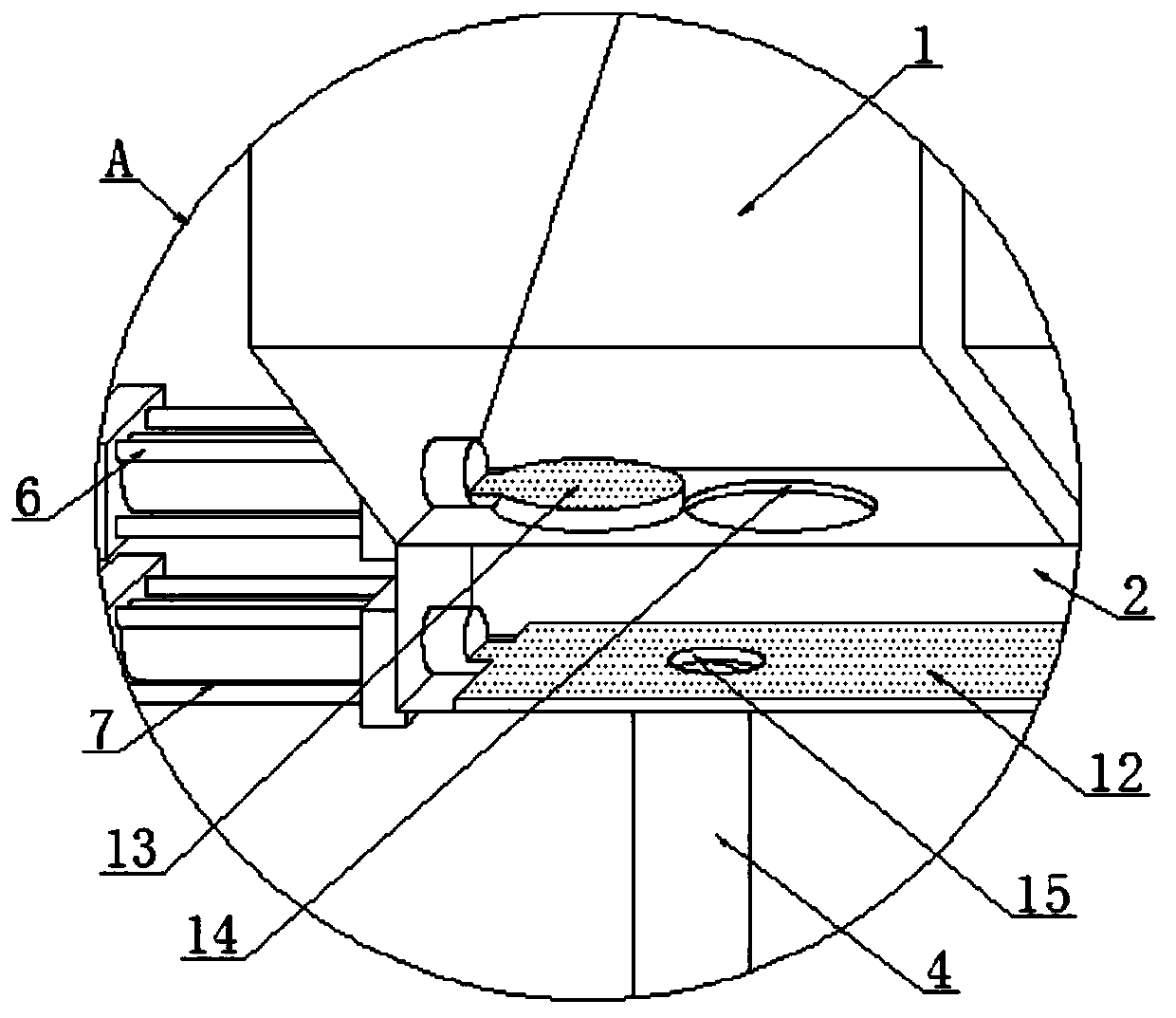
[0026] see Figure 1~5 In an embodiment of the present invention, a mechanical device includes a fertilizer storage and fertilization component 1, a leveling box 2 is welded to the lower end of the fertilizer storage and fertilization component 1, and a first cylinder 6 is installed on the outer surface of one side of the lower end of the fertilizer storage and fertilization component 1 (model is AXWF32-50-W5), the outer surface of one side of the screed box 2...


PUM


Abstract

The invention discloses a mechanical device. The mechanical device comprises a fertilizer storing and applying structural member, wherein a fertilizer evening box is welded to the lower end of the fertilizer storing and applying structural member, a first cylinder is mounted on the external surface of the lower end of one side of the fertilizer storing and applying structural member, and a secondcylinder is mounted on the external surface of one side of the fertilizer evening box; an anti-winding structural member is rotatably connected to the external surface of the lower end of the fertilizer evening box, and fertilizer applying rods are mounted on the lower surface of the fertilizer evening box in a penetrating manner; a pull rod is mounted on the front surface of the anti-winding structural member, and an anti-winding connecting sliding rod is connected to the inner side of the lower end of the anti-winding structural member in a sliding manner; and cover boards are rotatably connected to the upper surface of the fertilizer storing and applying structural member. According to the mechanical device disclosed by the invention, two kinds of fertilizers can be placed at the same time, selective fertilizer application can be performed, and the discharging speed can be quickly and conveniently adjusted; and the anti-winding structural member is arranged, and electrical adjustment of the discharging speed is realized. The mechanical device disclosed by the invention is simple in structure and small in volume.

Description

technical field [0001] The invention relates to the technical field of pull rod fertilization machinery, in particular to a mechanical device. Background technique [0002] Fertilization refers to the agricultural technical measures of applying fertilizers to the soil or spraying them on plants to provide the nutrients needed by plants and to maintain and improve soil fertility. The main purpose of fertilization is to increase crop yields, improve crop quality, fertilize soil and Improve economic benefits, so rational and scientific fertilization is one of the main means to ensure food security and maintain the sustainable development of agriculture. The mechanical device is used to fertilize by connecting the power device with a pull rod. Generally, it is a small fertilization mechanical device, which is convenient for the growth of plants. Fertilize. [0003] The Chinese patent discloses a mechanical device (authorized notification number CN207135460U). This patented tech...

Claims


Application Information

Patent Timeline
Patent Type & Authority Applications(China)
IPC IPC(8): A01C15/06
CPCA01C15/06
Inventor 陈栋
Owner JIASHAN LUOJIA FURNITURE CO LTD
Why Eureka
Try Eureka