Direct-current electric hand riveter

A riveting gun, electric technology, applied in the field of plate processing, can solve the problems of thin tube welding is easy to melt, tapping internal thread is easy to slip, easy to melt, etc., so as to facilitate the adaptation of large differences and prevent the force from being misdirected Sexuality, easy to achieve the effect of shock absorption requirements

Inactive Publication Date: 2020-04-28
雍小龙
View PDF0 Cites 0 Cited by
  • Summary
  • Abstract
  • Description
  • Claims
  • Application Information

AI Technical Summary

Problems solved by technology

Developed to solve the shortcomings of metal sheets and thin tubes that weld nuts are easy to melt, and tapping internal threads is easy to slip. It can rivet riveting products that do not require tapping internal threads and welding nuts. If the nut of a certain product needs to be installed outside , and the space inside is too small to let the pressure head of the sub-riveting machine enter for pressure riveting and methods such as budding cannot meet the strength requirements. In the field of pipe fastening, the pneumatic or manual riveting gun can be used for one-time riveting, which is convenient and firm; it replaces the traditional welding nut to make up for the deficiencies of thin metal plates, thin tube welding is fusible, and welding nuts are not smooth, but the existing riveting gun There are also the following problems:
[0003] When splicing and fixing a long flat plate, the riveti

Method used


Image

  • Direct-current electric hand riveter
  • Direct-current electric hand riveter
  • Direct-current electric hand riveter

Examples


Embodiment Construction

[0022] In order to make the technical means, creative features, goals and effects achieved by the present invention easy to understand, the present invention will be further described below in conjunction with specific embodiments.

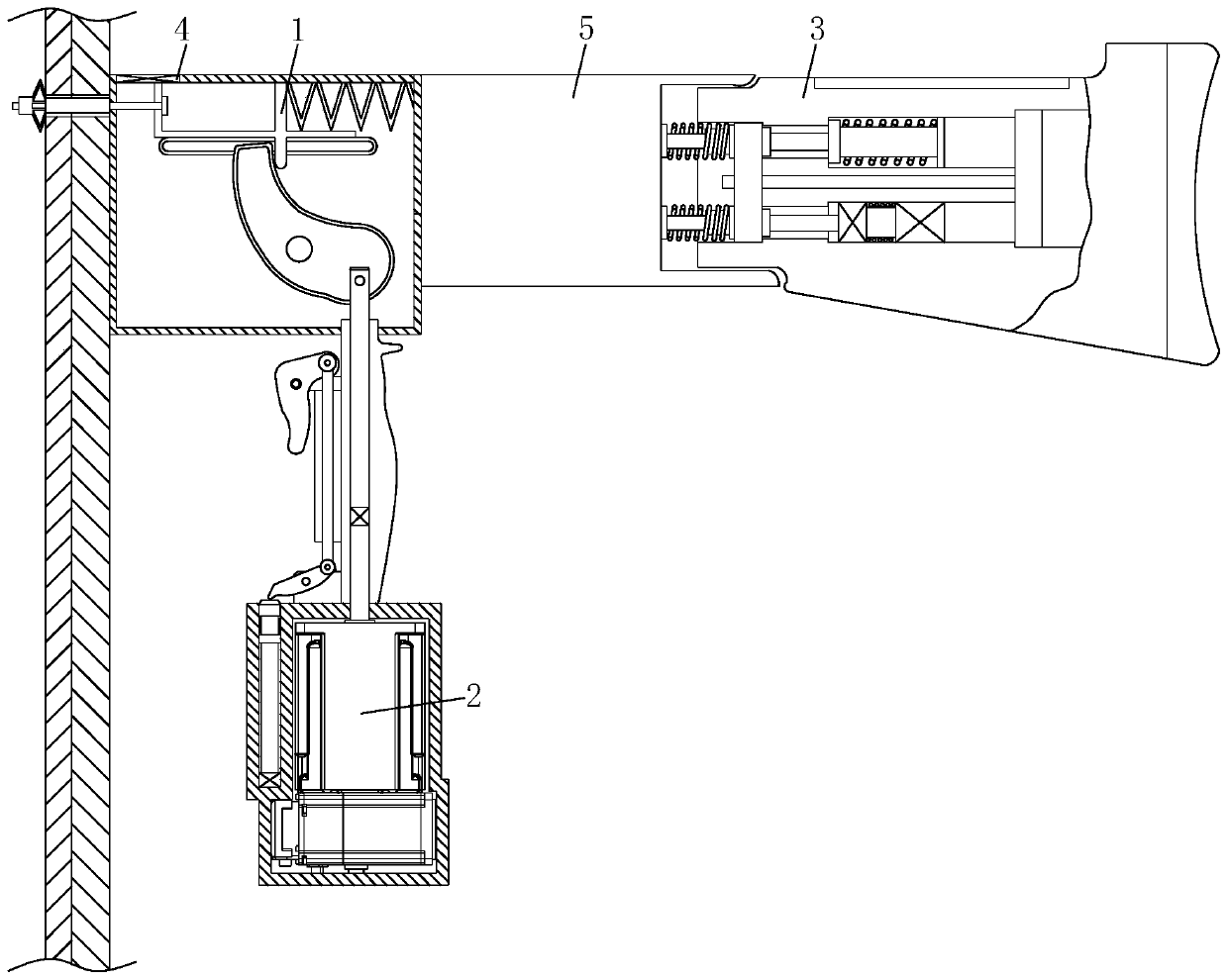
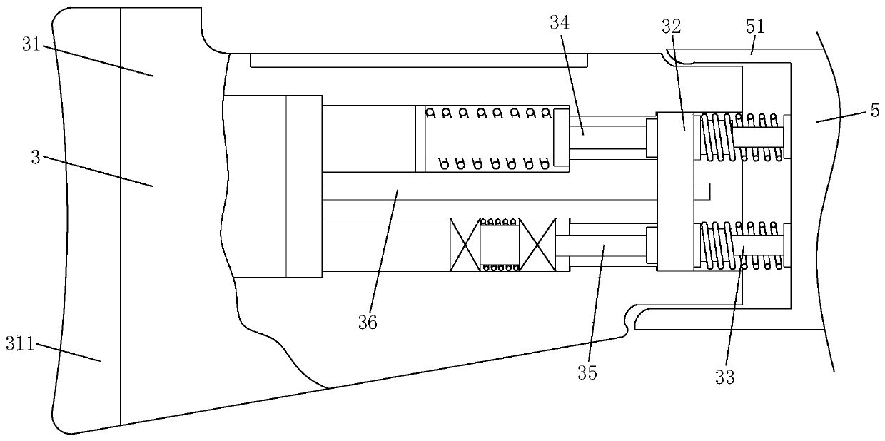
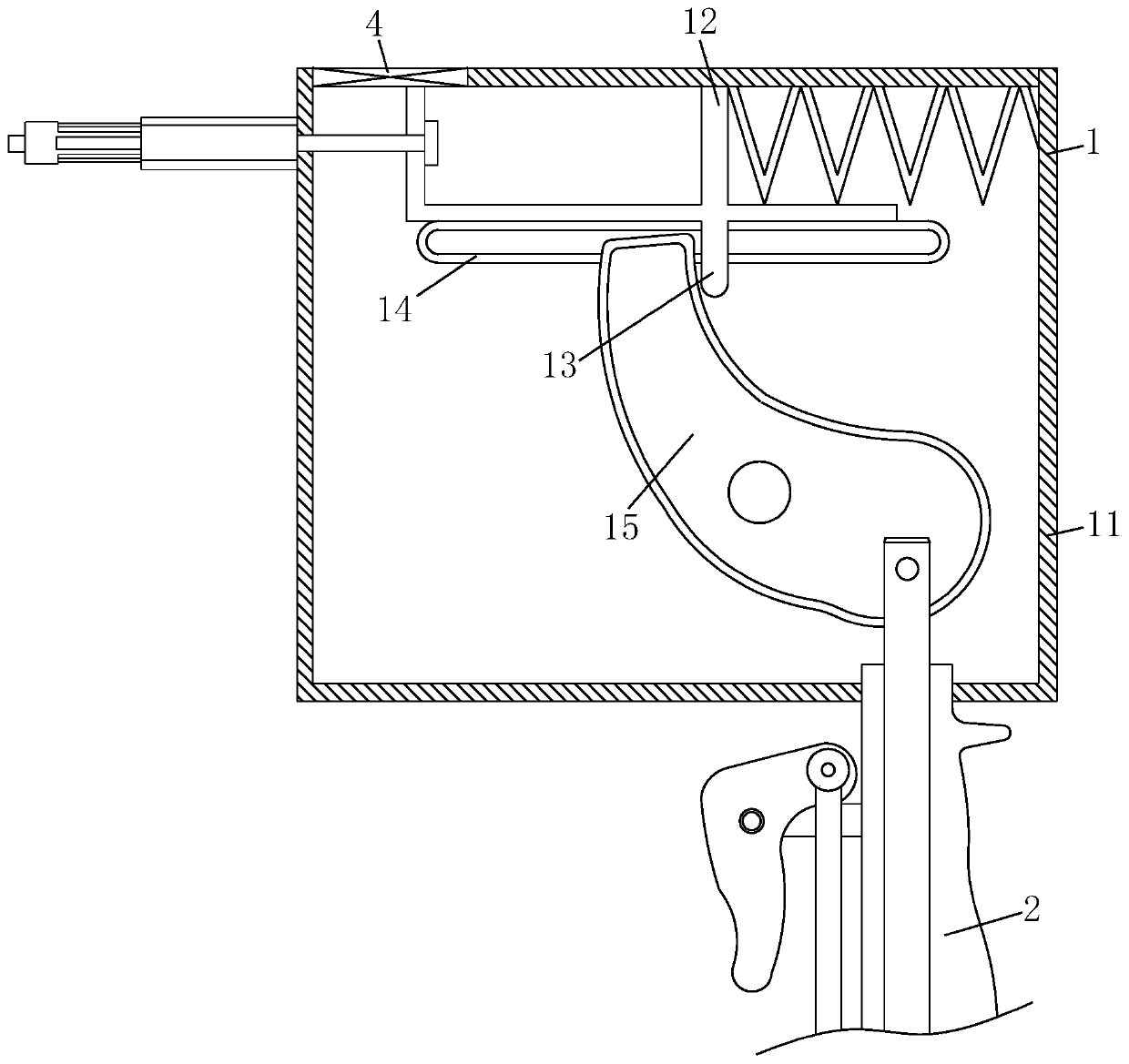
[0023] like Figure 1-Figure 5 As shown, a DC electric riveting gun according to the present invention includes a riveting assembly 1, a driving assembly 2, and a shock absorbing assembly 3. A clamping mechanism 4 is provided on one side of the top of the riveting assembly 1, and the riveting assembly 1 is provided with a clamping mechanism 4. The bottom of the riveting assembly 1 is provided with a driving assembly 2, the other side of the riveting assembly 1 is fixedly connected with a connecting arm 5, one side of the connecting arm 5 is fixedly connected with a wrapping sleeve 51, and the inner sleeve of the wrapping sleeve 51 A cushioning assembly 3 located on one side of the connecting arm 5 is connected, and a rivet is clamped in the clampi...


PUM


Abstract

The invention relates to the field of plate machining, in particular to a direct-current electric hand riveter. The hand riveter comprises a rivet pulling assembly, a driving assembly and a cushioningassembly, wherein a clamping mechanism is arranged on one side of a top of the rivet pulling assembly, the driving assembly is arranged at a bottom of the rivet pulling assembly, a connecting arm isfixedly connected to the other side of the rivet pulling assembly, a wrapping sleeve is fixedly connected to one side of the connecting arm, the cushioning assembly located on one side of the connecting arm is sleeved with the wrapping sleeve, and a rivet is clamped in the clamping mechanism. A tensioning block is arranged and used in combination with a deflection cam, an air cylinder is connectedwith a common rechargeable lithium battery, a trigger is pulled to enable the air cylinder to work, a connecting shaft is installed at an output end of the air cylinder, the deflection cam is pulleddownwards, and one side of a top of the deflection cam and a limiting suspension plate are pressed and poked, so that the rivet is tensioned through the tensioning block, automatic rivet pulling operation on the rivet is advantageously performed, consumed huge external force needed by manual force application is avoided, manpower is saved, work is stable, and non-directionality of force applied bythe manual external force during rivet pulling is prevented.

Description

technical field [0001] The invention relates to the field of plate processing, in particular to a DC electric riveting gun. Background technique [0002] Riveting guns are used for fastening and riveting of various metal sheets, pipes and other manufacturing industries. At present, they are widely used in riveting of electromechanical and light industrial products such as elevators, switches, instruments, furniture, and decoration. Developed to solve the shortcomings of metal sheets and thin tubes that weld nuts are easy to melt, and tapping internal threads is easy to slip. It can rivet riveting products that do not require tapping internal threads and welding nuts. If the nut of a certain product needs to be installed outside , and the space inside is too small to let the pressure head of the sub-riveting machine enter for pressure riveting and methods such as budding cannot meet the strength requirements. In the field of pipe fastening, the pneumatic or manual riveting g...

Claims


Application Information

Patent Timeline
IPC IPC(8): B21J15/10B21J15/38
CPCB21J15/105B21J15/38
Inventor 雍小龙孙安杰王康
Owner 雍小龙
Why Eureka
Try Eureka