Steel plate net punching and shearing machine

A technology of punching and shearing machine and expanded metal mesh, which is applied to shearing device, shearing machine equipment, feeding device, etc., can solve the problems of complex transmission, and achieve the effect of flexible use, simple structure and equipment cost saving.

Inactive Publication Date: 2020-04-28
浙江高盛钢结构有限公司
View PDF12 Cites 9 Cited by
  • Summary
  • Abstract
  • Description
  • Claims
  • Application Information

AI Technical Summary

Problems solved by technology

[0005] When the above-mentioned expanded metal punching and shearing machine is used to process the expanded metal, in order to ensure that the feeding mechanism can keep up with the synchronous movement of the tool holder, an ecce

Method used


Image

  • Steel plate net punching and shearing machine
  • Steel plate net punching and shearing machine
  • Steel plate net punching and shearing machine

Examples


Embodiment 1

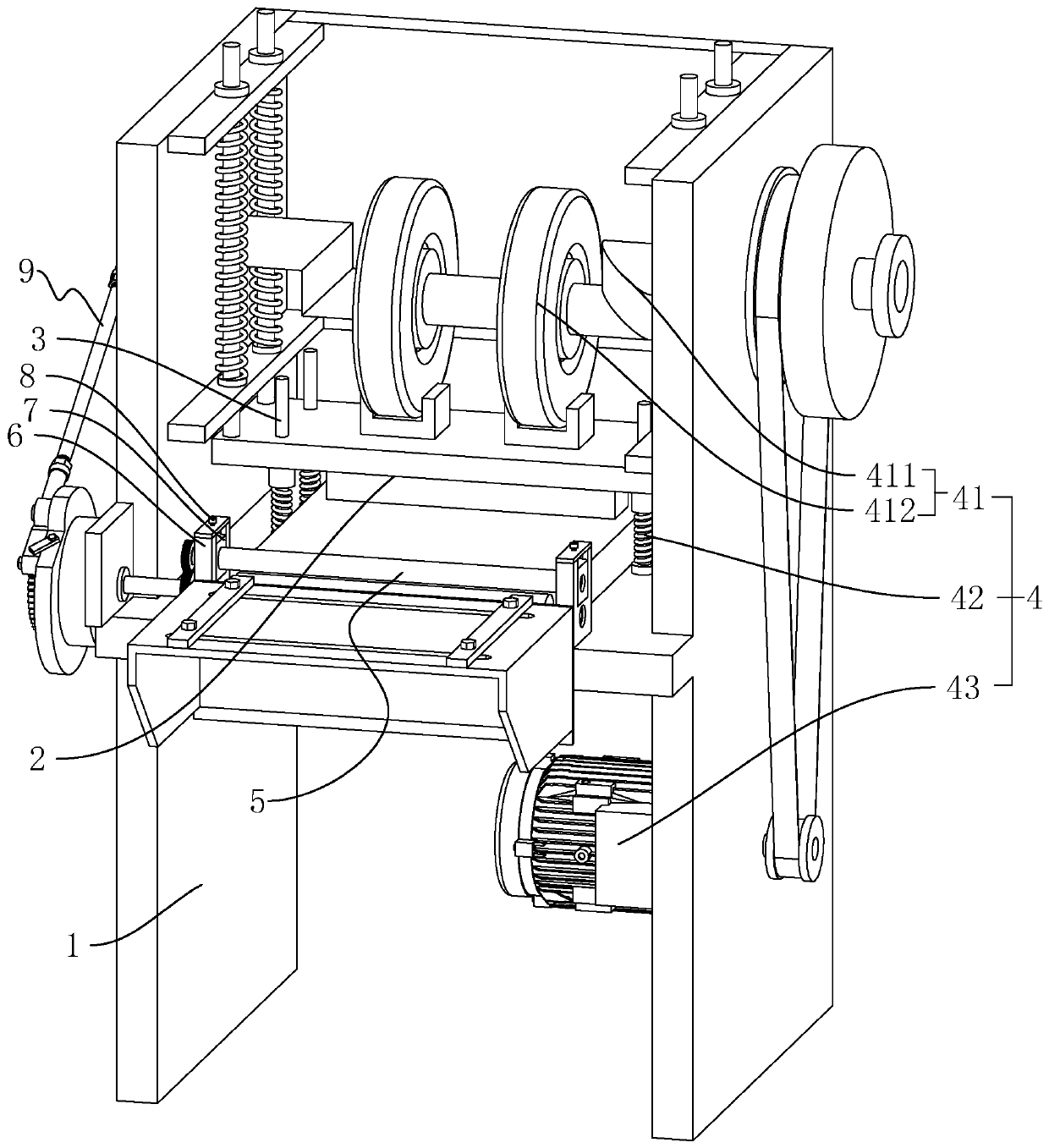
[0039] An expanded metal punching and shearing machine, such as figure 1As shown, it includes a frame 1 on which an upper knife rest 2 slides vertically, and the lower end surface of the upper knife rest 2 is correspondingly equipped with a blade for punching and shearing. Also be vertically fixed with some guide shafts 3 on the frame 1, move up and down by guide shaft 3 guiding upper knife rest 2. The frame 1 is also provided with a driving device 4 , the driving device 4 includes a cam mechanism 41 rotatably connected to the frame 1 , a return spring 42 arranged on the frame 1 , and a driving motor 43 arranged on the frame 1 . The cam mechanism 41 is located above the upper knife rest 2, and the return spring 42 is sleeved on the guide shaft 3 and pressed against the lower end surface of the upper knife rest 2. The elastic force of the return spring 42 makes the return spring 42 press against the upper knife rest 2 so that the upper The upper end surface of the knife rest 2...

Embodiment 2

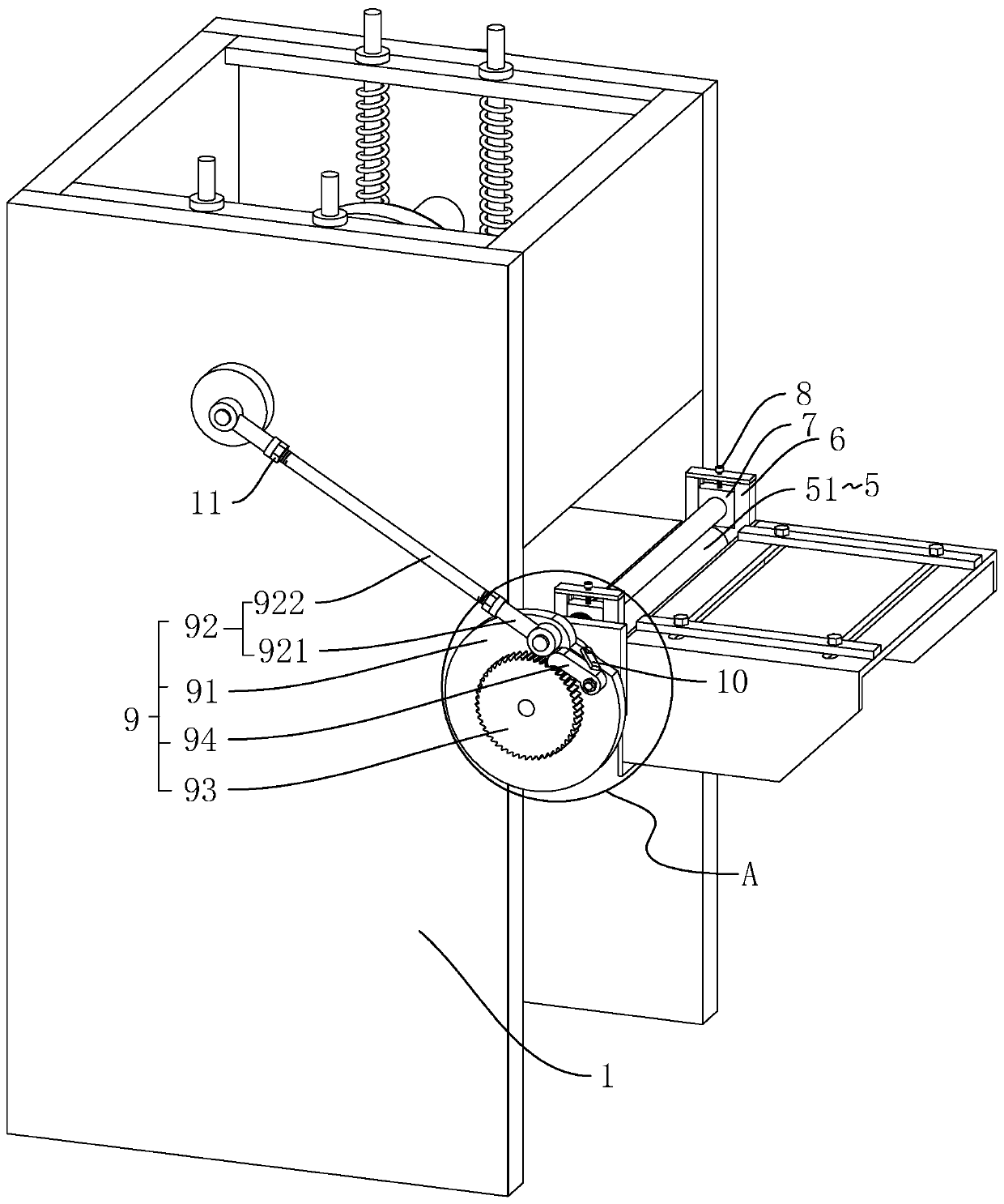
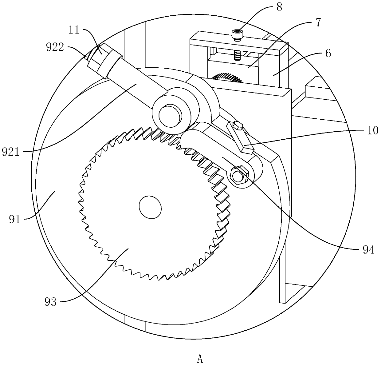
[0048] An expanded metal punching and shearing machine, such as Figure 4 , Figure 5 As shown, the difference from Embodiment 1 is that the end surface of the cam mechanism 41 connected with the hinge rod 92 is also provided with an adjustment assembly 12 . The adjustment assembly 12 includes an adjustment block 121 that is slidably connected to the cam mechanism 41 in a direction perpendicular to the rotation axis of the cam mechanism 41, an adjustment screw 122 that is threaded on the adjustment block 121 and is rotatably connected with the cam mechanism 41, and the adjustment block 121 is also A hinged column 13 is fixed, and the hinged rod 92 is hinged with the cam mechanism 41 by being hinged with the hinged column 13 . The guide rail 14 is correspondingly fixed on the cam mechanism 41 , and the adjustment block 121 is provided with a chute 15 for the guide rail 14 to slide. The adjustment block 121 slides through the cooperation of the guide rail 14 and the chute 15 . ...


PUM


Abstract

The invention discloses a steel plate net punching and shearing machine, and relates to the technical field of steel plate net production. The steel plate net punching and shearing machine comprises arack, an upper tool rest is slidably arranged on the rack, a driving device is further arranged and comprises a cam mechanism, a reset spring and a driving motor which are rotationally connected to the rack, a feeding assembly is further arranged and comprises two conveying rollers, a transmission mechanism is connected between the cam mechanism and one of the conveying rollers and comprises a rotating part, a hinging rod, a ratchet wheel and a ratchet matched with the ratchet wheel, the ratchet wheel is coaxially and fixedly connected with the corresponding conveying roller, the rotating part is rotationally arranged relative to the ratchet wheel, the rotating axis of the rotating part is arranged coaxially with the ratchet wheel, the ratchet is correspondingly hinged to the rotating part, one end of the hinging rod is hinged to the rotating part, the other end of the hinging rod is hinged to the cam mechanism, and the hinging axis of the hinging rod and the cam mechanism and the rotating axis of the cam mechanism are arranged in a staggered mode. Through cooperation of the hinging rod, the rotating part, the ratchet wheel and the ratchet, using of a clutch is avoided, and the overall structure is simpler.

Description

technical field [0001] The invention relates to the technical field of expanded metal production, more specifically, it relates to an expanded metal punching and shearing machine. Background technique [0002] Foamed cement is also called foamed cement. The foaming agent is fully foamed mechanically through the foaming system of the foaming machine, and the foam is evenly mixed with the cement slurry, and then cast-in-place construction is carried out through the pumping system of the foaming machine. Or mold forming, a new type of lightweight thermal insulation material containing a large number of closed pores formed by natural curing. [0003] In the field of concrete, due to the insufficient strength of foam cement, the structure is strengthened by wrapping steel mesh on the outside of foam cement. The forming of expanded metal mesh is generally processed by the metal sheet through the expanded metal mesh punching and shearing machine, and then stretched to form a mesh-...

Claims


Application Information

Patent Timeline
IPC IPC(8): B23D15/04B23D15/12B21D43/09
CPCB21D43/09B23D15/04B23D15/12
Inventor 李之强黎洪赵红运
Owner 浙江高盛钢结构有限公司
Why Eureka
Try Eureka