

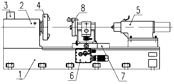
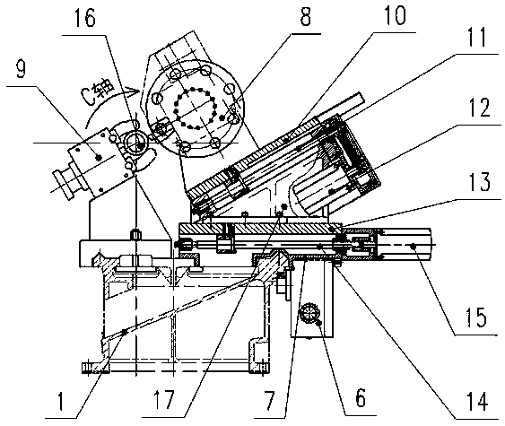
Computerized numerical control turning center with flat bed and slant tool rest
A turning center, flat bed technology, applied in the direction of large fixed members, metal processing machinery parts, metal processing equipment, etc., can solve the problems of poor safety, poor precision, low efficiency of processing methods, etc.
- Summary
- Abstract
- Description
- Claims
- Application Information
AI Technical Summary
Problems solved by technology
Method used
Image

Examples
Embodiment Construction
[0018] The technical solutions in the embodiments of the present application will be clearly and completely described below in conjunction with the accompanying drawings in the embodiments of the present application. Obviously, the described embodiments are only some of the embodiments of the present application, not all of them. Based on the embodiments of the present application, all other embodiments obtained by persons of ordinary skill in the art without making creative efforts belong to the protection scope of the present application.
[0019] In the description of the present invention, it should be understood that the orientation or positional relationship indicated by the terms "inner", "outer", "left", and "right" is based on the orientation or positional relationship shown in the drawings, and is only for convenience The present invention is described and simplified descriptions do not indicate or imply that the device or element referred to must have a specific orie...
PUM
 Abstract
Description
Claims
Application Information