
Universal charging device for unmanned aerial vehicle

A charging device and unmanned aerial vehicle technology, applied in the direction of circuit devices, battery circuit devices, current collectors, etc., can solve the problems of multiple installation spaces, limited application range, and large cost investment

Active Publication Date: 2019-03-15
深圳市鑫疆基业科技有限责任公司
View PDF6 Cites 3 Cited by
  • Summary
  • Abstract
  • Description
  • Claims
  • Application Information

AI Technical Summary

Problems solved by technology

[0003]The existing UAV battery charger only has the function of outputting one voltage to charge the battery. For users, the power output by the charger can also ensure the normal charging of the battery; but for users with a large number of UAV batteries with different voltages, it is necessary to equip a large number of chargers with different output voltages. In this way, not only the large number of chargers with different voltage outputs will lead to a large cost investment, but also occupy more installation space. In practical applications, if a charger with a voltage output occurs After a failure, the battery of the drone with a corresponding voltage cannot be charged with other chargers with different voltage outputs (the output voltage of other chargers does not match the voltage of the battery)
To sum up, the existing UAV chargers cannot adapt to output multiple voltages to charge UAV batteries with different voltages, and the application range is limited.

Method used


Image

  • Universal charging device for unmanned aerial vehicle
  • Universal charging device for unmanned aerial vehicle

Examples


Embodiment Construction

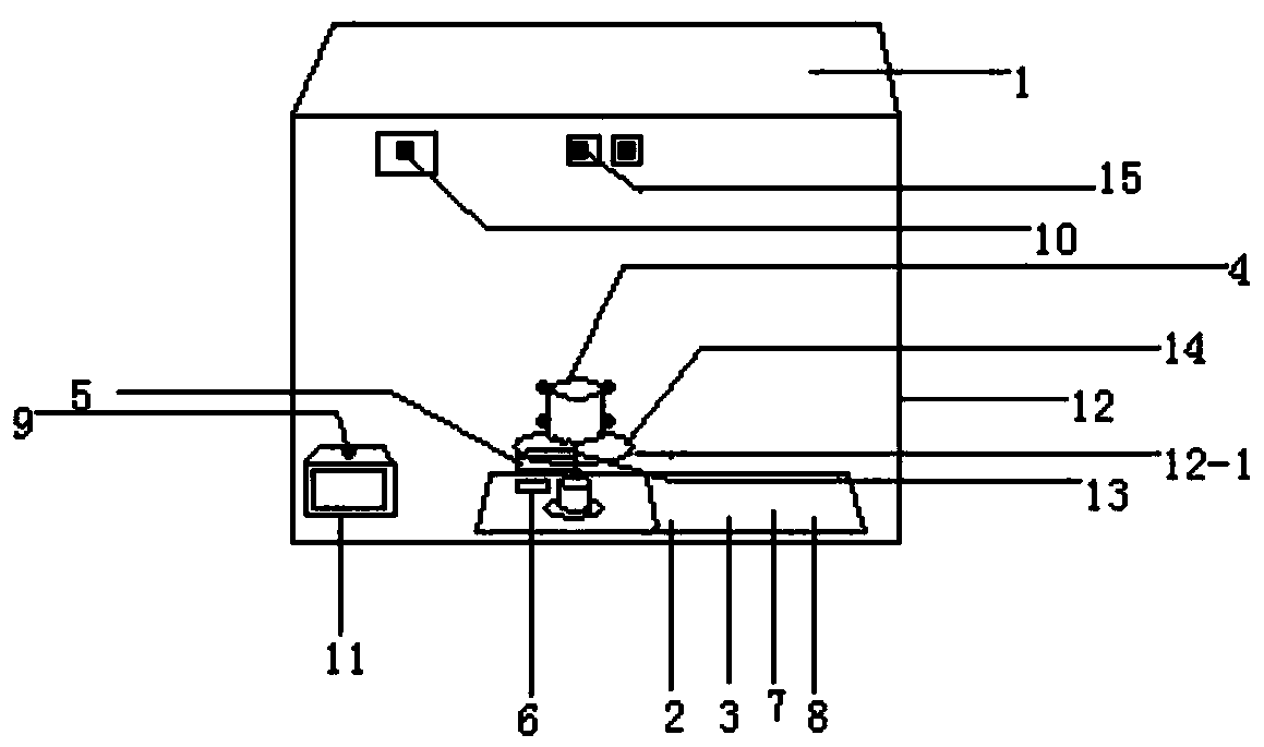
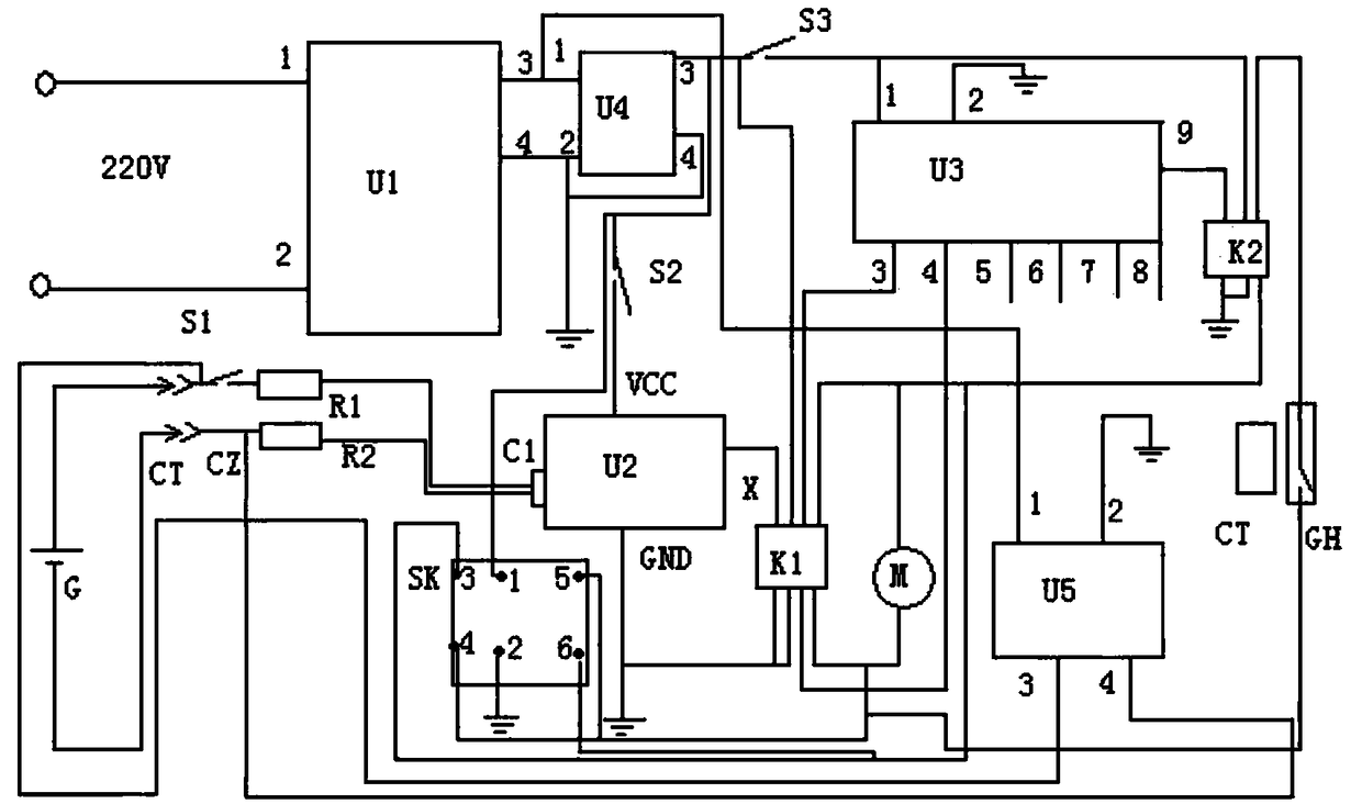
[0018] figure 1As shown in , a universal charging device for drones, including 48V power charger body 1 (in order to realize normal charging of 48V battery, the actual output of 48V power charger body 1 is higher than 48V, generally around 54V), DC to DC module 2. Voltage regulation module 3, motor deceleration mechanism 4, strip permanent magnet 5 and reed switch 6, also has detection circuit 7, time circuit 8, trigger switch 9, manual power switch 10, charging socket 11 behind the charger body There is an opening on the upper part of the side end. The trigger switch 9 is a jog type normally open contact micro switch. The trigger switch 9 is installed in the opening. The button of the trigger switch 9 faces the front side of the charging socket 11. After all the battery charging plugs are inserted into the charging socket, the rear end of the charging plug just presses the button of the trigger switch 9, and the two normally open contacts inside the trigger switch 9 are conne...


PUM


Abstract

The invention discloses a universal charging device for an unmanned aerial vehicle, and the device comprises a power charger body, a DC-DC module, a voltage adjustment module, a motor speed reductionmechanism, a bar-shaped permanent magnet, and a reed pipe. The device is also provided with a detection circuit, a time circuit, a trigger switch, and a hand-operated power switch. The trigger switchis installed in a charging socket of the charger body, and the DC-DC module, the voltage adjustment module, the detection circuit, the time circuit and the reed pipe are installed at the lower part ofthe interior of the housing of the charger body, and are connected with the motor speed reduction mechanism and the hand-operated power switch through wires. The hand-operated power switch is installed in the front upper end of the housing, and the housing of the motor speed reduction mechanism is installed at the central part of the rear lower end of the interior of the housing of the charger body. A power output shaft of the motor speed reduction mechanism and an adjustment handle sleeve of the voltage adjustment module are sleeved together, and the right end of the bar-shaped permanent magnet is installed at the left side of a connecting pipe. The device can achieve the effective charging of the UAV storage batteries with various voltages, is wider in application range, and brings moreconvenience to a user.

Description

technical field [0001] The invention relates to the field of supporting equipment for drones, in particular to a universal charging device for drones. technical background [0002] Due to its flexibility and ease of use, drones are increasingly used in civil, industrial, and military fields, such as aerial photography, surveying and mapping, and agricultural plant protection. The power device of drones is generally divided into electric drive and internal combustion engine drive. Compared with internal combustion engine drive, electric drive has a lower cost, lower failure rate and more convenient use, so it is widely used. The drone is driven by electricity, and the battery is the prerequisite to ensure the normal operation of the drone. Therefore, when the battery of the drone is out of power, the user needs to use a charger to charge the battery. The voltages of existing drone batteries are generally representative of 12V, 24V, and 36V, so batteries of different voltages...

Claims


Application Information

Patent Timeline
Patent Type & Authority Applications(China)
IPC IPC(8): H02J7/04
CPCH02J7/045Y02T10/70
Inventor 陈华勋
Owner 深圳市鑫疆基业科技有限责任公司
Learn More