Hot runner flow dividing and side pouring method and mold

A technology of hot runners and molds, applied in the direction of coating, etc., can solve the problems of only one or two moldings, difficulty in realizing automatic de-gate, high labor costs, etc., achieve stable shunt effect, realize mold protection, and stable workpiece quality Effect

Inactive Publication Date: 2020-04-28
深圳市三阳科技技术有限公司
View PDF3 Cites 0 Cited by
  • Summary
  • Abstract
  • Description
  • Claims
  • Application Information

AI Technical Summary

Problems solved by technology

[0002] In recent years, the hot runner process has been widely used due to its advantages of simple mold structure, easy molding, and fast molding speed. The structure of the hot runner is complex, and traditional glue injection can only use point gates or submerged gates. For mold cavities With a large number of moulds, it is difficult to realize automatic gate removal, the molding cycle is long, and

Method used


Image

  • Hot runner flow dividing and side pouring method and mold
  • Hot runner flow dividing and side pouring method and mold
  • Hot runner flow dividing and side pouring method and mold

Examples


Embodiment Construction

[0065] Below in conjunction with accompanying drawing and embodiment the present invention will be further described:

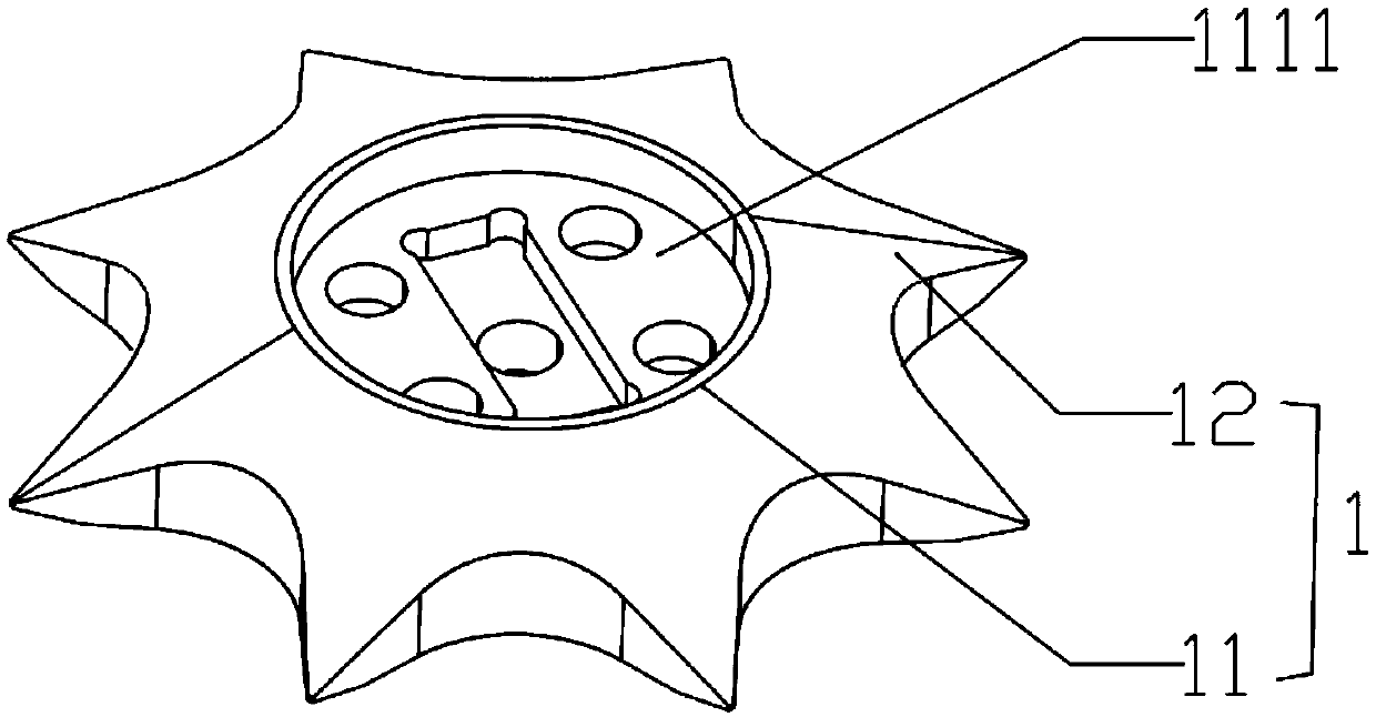
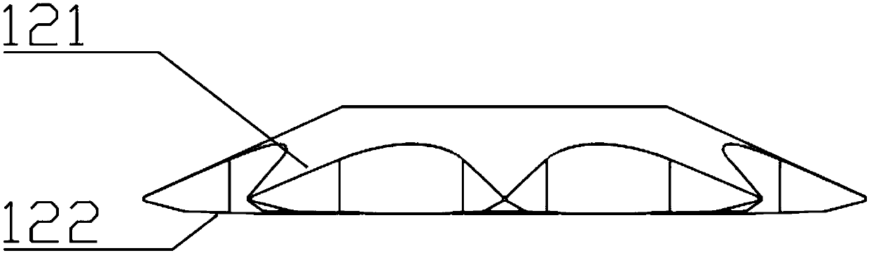
[0066] like figure 1 As shown, a hot runner distribution device includes a hot nozzle distribution block 1. The hot nozzle distribution block 1 includes a main body 11, and the main body 11 is provided with more than two feed distribution claws 12 extending outward; the feed distribution claw The cross-sectional area of ​​12 gradually becomes smaller along the extension direction, and the end of the feed splitter claw 12 can extend into the side gate and cooperate with the side gate. Here, more than two feed splitting claws include two or more situations. In this embodiment, more than two feed splitting claws are set to two. Set to two or more.

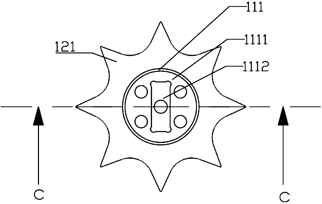
[0067] Further, such as Figure 2 to Figure 4 , the main body 11 includes an upper surface 111 and a lower surface 112, the upper surface 111 is provided with a split inlet 1111; the split inlet 1111 is connected ...


PUM


Abstract

The invention discloses a hot runner flow dividing and side pouring method and mold. The method comprises the steps of (1) arranging a pouring gate base plate, forming a pouring gate groove in the pouring gate base plate, and forming two or more flow dividing transition grooves or flow dividing ports in the edge of the pouring gate groove; 2) arranging a flow dividing cavity at the tail ends of the flow dividing transition grooves or the flow dividing ports, and communicating the tail end of the flow dividing cavity with a side pouring gate; and 3) communicating the side pouring gate with a molding cavity, and carrying out side pouring molding. By means of the hot runner side pouring method and the hot runner mold provided by the invention, the hot runner molding period can be greatly shortened, for example, the one-step molding of a glass bottle plastic cover can be reduced by about 2 seconds, and the yield can be increased by 15% or above. Meanwhile, due to the implementation of thehot runner side pouring gate, the structure of a multi-molding cavity hot runner is simplified, the product quality is more stable, the number of mold cavities can be increased, and the yield is increased. Due to the side pouring mode, there is no degraded material, the labor cost is reduced, materials are saved, the environment is protected, and considerable economic benefits are brought.

Description

technical field [0001] The invention relates to the field of plastic molding, in particular to a method and a mold for split flow and side casting of a hot runner. Background technique [0002] In recent years, the hot runner process has been widely used due to its advantages of simple mold structure, easy molding, and fast molding speed. The structure of the hot runner is complex, and traditional glue injection can only use point gates or submerged gates. For mold cavities With a large number of molds, it is difficult to realize automatic gate removal, the molding cycle is long, and the labor cost is high. At present, the side pouring method is widely used as a relatively easy way to realize automatic gate removal. However, due to the limitations of injection pressure and injection balance in the existing hot runner side pouring method, often only one or two injections can be made at one time. Therefore, there are defects such as long molding cycle and low production effic...

Claims


Application Information

Patent Timeline
IPC IPC(8): B29C45/27B29C45/14B29C45/73
CPCB29C45/14B29C45/27B29C45/2737B29C2045/2766
Inventor 胡波
Owner 深圳市三阳科技技术有限公司
Why Eureka
Try Eureka