
An injection joint for injection molding machine with pressure supply design

A technology of injection molding machine and pressure supply, which is applied in the field of injection molding machine design, can solve problems such as product defects, and achieve the effects of simple use, high practical value, and labor saving

Active Publication Date: 2021-05-25
东莞市锦洲塑胶制品有限公司
View PDF0 Cites 0 Cited by
  • Summary
  • Abstract
  • Description
  • Claims
  • Application Information

AI Technical Summary

Problems solved by technology

However, the pressure provided by the conveying auger itself is small. If the mold structure is complex, higher pressure is required to press the material into the mold. When the pressure is insufficient, the material cannot fully fill the inside of the mold, and the resulting product will be poor. serious flaws

Method used


Image

  • An injection joint for injection molding machine with pressure supply design
  • An injection joint for injection molding machine with pressure supply design
  • An injection joint for injection molding machine with pressure supply design

Examples


Embodiment Construction

[0021] The following will clearly and completely describe the technical solutions in the embodiments of the present invention with reference to the accompanying drawings in the embodiments of the present invention. Obviously, the described embodiments are only some, not all, embodiments of the present invention. Based on the technical solutions in the present invention, all other embodiments obtained by persons of ordinary skill in the art without making creative efforts belong to the protection scope of the present invention.

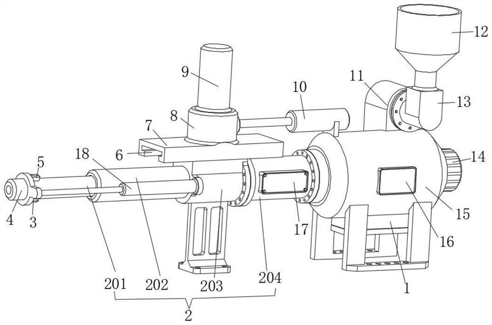
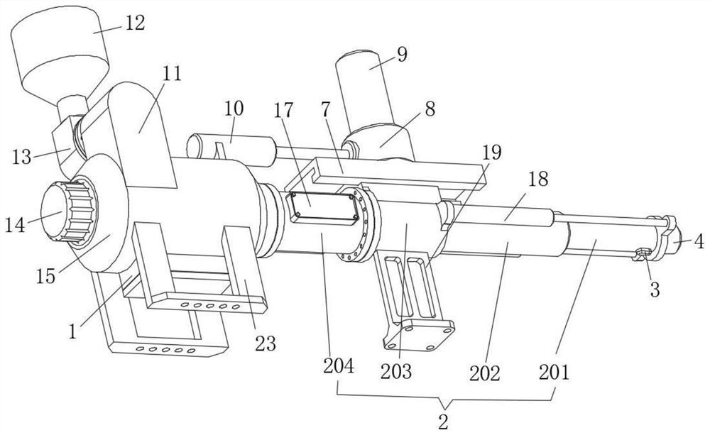
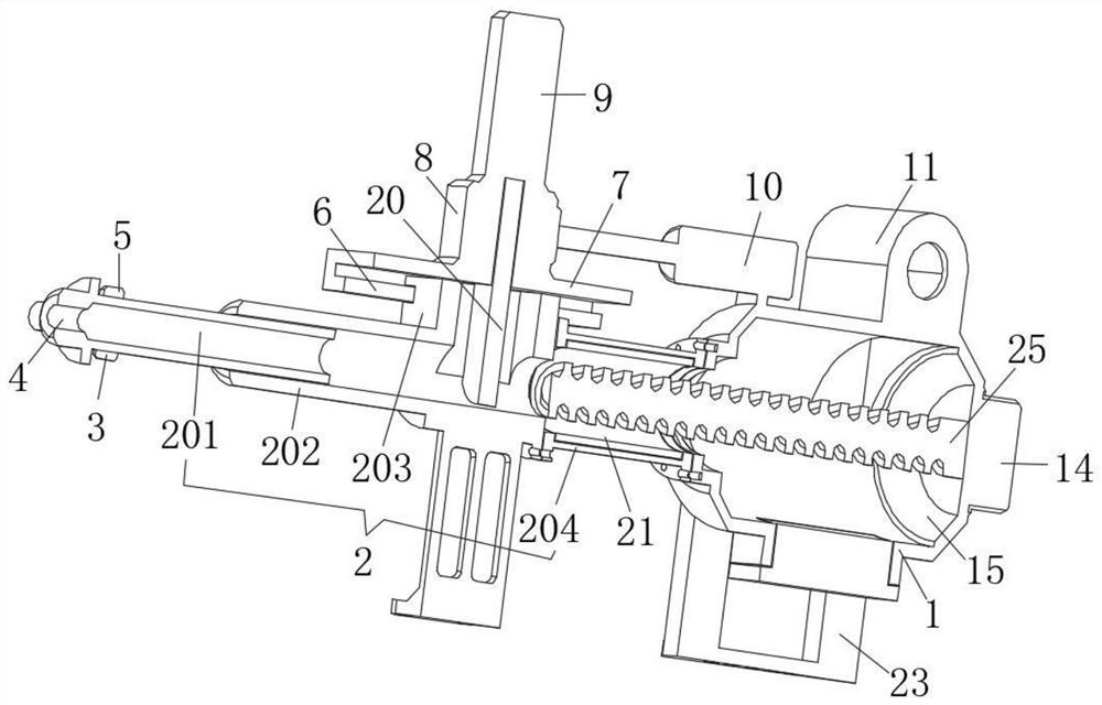
[0022] see Figure 1 to Figure 4 , the present invention provides a technical solution: an injection joint for an injection molding machine that adopts a pressure supply design, including an injection tube 2, the right side of which is installed on a feeder 15, and the feeder 15 is integrally formed with a butt joint Seat 11, on the docking seat 11, a feeding seat 13 is fixedly installed by bolts, on the feeding seat 13, a barrel 12 is fixedly installe...


PUM


Abstract

The invention relates to the technical field of injection molding machine design, in particular to an injection joint for an injection molding machine that adopts a pressure supply design, including an injection tube, the injection tube includes a heating tube that is fixed and installed with a feeder through bolts, and the left side of the heating tube passes through The bolts are installed with a pressure supply pipe, the left side of the pressure supply pipe is welded and installed with a butt joint, and a telescopic tube is inserted into the butt joint. The beneficial effect is: the device can provide higher extrusion pressure by driving the push rod and the push plate, so that the material can be more fully filled into the mold, effectively avoiding product defects caused by insufficient extrusion pressure The problem is that the device is easy to use, can adapt to molds of different sizes, and only needs to set the extrusion pressure and extrusion cycle in the controller to complete the injection extrusion automatically, which effectively saves manpower and has a lot of advantages. High practical value.

Description

technical field [0001] The invention relates to the field of injection molding machine design, in particular to an injection molding joint for an injection molding machine adopting a pressure supply design. Background technique [0002] Injection molding machine is a kind of equipment used to add materials to the injection mold to form plastic products of various shapes. The injection joint of the injection molding machine is used to feed the material into the mold. The existing injection joints generally only use conveying augers To provide the pressure for the material to move forward. However, the pressure provided by the conveying auger itself is small. If the mold structure is complex, higher pressure is required to press the material into the mold. When the pressure is insufficient, the material cannot fully fill the inside of the mold, and the resulting product will be poor. Serious flaws can occur. [0003] If we can invent a new type of joint for injection molding...

Claims


Application Information

Patent Timeline
Patent Type & Authority Patents(China)
IPC IPC(8): B29C45/77B29C45/03B29C45/47B29C45/58
CPCB29C45/03B29C45/47B29C45/58B29C45/77
Inventor 姚夏康
Owner 东莞市锦洲塑胶制品有限公司
Learn More