Lifting equipment applied to construction of auxiliary electric power circuit

A technology for line erection and auxiliary power, applied in the direction of lifting equipment safety devices, lifting devices, etc., can solve the problems of the lifting box without protective devices, the risk of falling, and the complex mechanical structure, so as to avoid accidental falls and reduce equipment usage. Quantity, the effect of enhancing the safety of use

Active Publication Date: 2020-04-28
JIANGSU POWER TRANSMISSION & DISTRIBUTION CO LTD
View PDF10 Cites 0 Cited by
  • Summary
  • Abstract
  • Description
  • Claims
  • Application Information

AI Technical Summary

Problems solved by technology

[0005] The above-mentioned patent has the following disadvantages: the height of the support plate is determined by the rising height of the lifting box, so the height of the support plate is relatively high, which causes certain troubles for transportation and storage; it is realized by multiple components such as guide rollers, steering rollers, and winding rollers. The mechanical structure of the lifting box is too complicated, and after the lifting box is lifted and lowered, it is fixed by the motor to resist torsion, and there is a risk of falling; there is no protective device on the lifting box, and construction personnel also have certain safety risks during the construction process

Method used


Image

  • Lifting equipment applied to construction of auxiliary electric power circuit
  • Lifting equipment applied to construction of auxiliary electric power circuit
  • Lifting equipment applied to construction of auxiliary electric power circuit

Examples


Embodiment 1

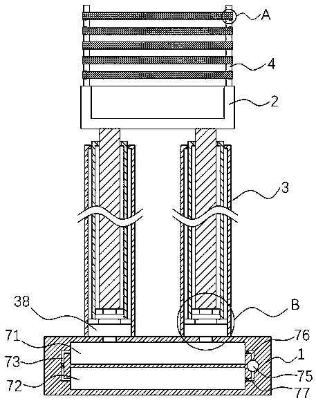
[0031] refer to Figure 1-4 , a lifting device applied to the erection of auxiliary power lines, comprising a lifting box 2 and a bottom plate 1 arranged up and down, and a lifting member 3 is arranged between the bottom plate 1 and the lifting box 2;

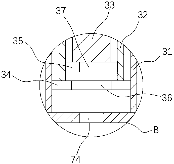
[0032] Specifically, the lifting member 3 includes a first connecting cylinder 31 , a second connecting cylinder 32 and a third connecting column 33 which are nested in sequence from outside to inside, and the first connecting cylinder 31 , the second connecting cylinder 32 and the third connecting cylinder 31 The columns 33 are all closed at the upper end and open at the lower end. The upper end of the third connecting column 33 runs through the second connecting cylinder 32, and the upper end of the second connecting cylinder 32 penetrates the first connecting cylinder 31. The lower end of the third connecting column 33 is fixedly connected with The second piston plate 35, and the second piston plate 35 is vertically sealed a...

Embodiment 2

[0038] refer to Figure 6-7 The difference between this embodiment and Embodiment 1 is that the jacking device includes a permanent magnet block 92 embedded in the lower end of the lifting box 2 and an electromagnetic block 91 embedded in the upper end of the bottom plate 1, and the electromagnetic block 91 and the permanent magnet block The positions of 92 are corresponding and mutually repelling. The lift box 2 is on the opposite side of the bottom plate 1 and is sealed and fixedly connected with the telescopic capsule body 93 on the outside of the electromagnetic block 91 and the permanent magnet block 92. A potentiometer 94 is provided on one side of the bottom plate 1. The electromagnetic block 91 and the potentiometer 94 are electrically connected to the external power supply, and the jacking cavity 38 is an unsealed space.

[0039] In this embodiment, the jacking cavity 38 is equal to the external atmospheric pressure. When it needs to be used, the electromagnetic block...

Embodiment 3

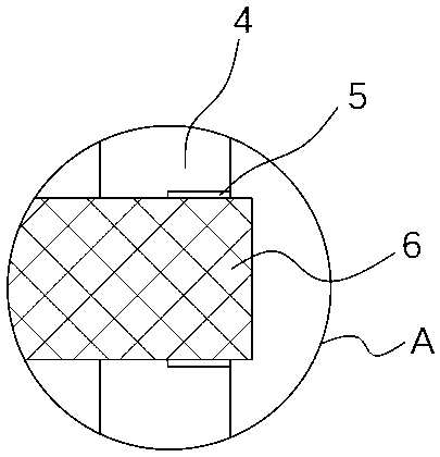
[0043] refer to figure 1 and Figure 4 , as an improvement to the above-mentioned embodiment 1 and embodiment 2: the upper end of the lifting box 2 is fixedly connected with four rectangularly arranged top columns 4, and the outer sides of the four top columns 4 are equidistantly provided with a plurality of protections from top to bottom. The protective piece includes an arc-shaped notch 5 set on the outside of the top column 4, and a plurality of notches 5 are fixedly sleeved with an elastic protective net 6. The elastic protective net 6 is made of insulating rubber material, similar to a boxing guardrail. .

[0044] In this embodiment, the elastic protective net 6 is fixedly socketed at the gaps 5 of the plurality of top columns 4 to protect the upper end of the lifting box 2, so as to avoid the accidental fall of the staff during the line erection process and enhance the safety of use sex.


PUM


Abstract

The invention discloses lifting equipment applied to construction of an auxiliary electric power circuit. The lifting equipment comprises a lifting case and a bottom plate which are arranged up and down, and lifting parts are arranged between the bottom plate and the lifting case. Each lifting part comprises a first connecting barrel, a second connecting barrel and a third connecting column, all of which are sequentially connected in a sleeved manner from outside to inside. Each of the first connecting barrels, the second connecting barrels and the third connecting columns is of a structure with the upper end being closed and the lower end being opened. The upper end of each third connecting column penetrates through the corresponding second connecting barrel, and the upper end of each second connecting barrel penetrates through the corresponding first connecting barrel. The lifting equipment has the advantages that the lifting height of the lifting case depends on the sum of lengths of the first connecting barrels, the second connecting barrels and the third connecting columns; the telescopic structure is adopted, and the situation that transporting is influenced due to too largeheight in the traditional technology is greatly reduced; a hydraulic drive manner is adopted and replaces multiple mechanical structures in the traditional technology to achieve ascending and descending of the lifting case; and the structure is simple, and the situation that the equipment is worn due to long-time use is avoided.

Description

technical field [0001] The invention relates to the field of electric power auxiliary technology, in particular to a lifting device applied to auxiliary power line erection. Background technique [0002] Power lines refer to the lines used to transmit electric energy between power plants, substations and power users. It is an important part of the power supply system and is responsible for the task of transmitting and distributing electrical energy. [0003] During the erection of power lines, it is usually necessary to manually climb the pole to a certain height. At the same time, the staff puts the erection tools and accessories in the backpack, or the construction personnel need to be pulled up with ropes on the top of the pole. The construction personnel in the above process It is inconvenient to move and has a high risk factor. [0004] After retrieval, the Chinese Patent Publication No. CN208561531U discloses a lifting device for auxiliary power line erection, includ...

Claims


Application Information

Patent Timeline
Patent Type & Authority Applications(China)
IPC IPC(8): B66F11/04B66F13/00B66F17/00
CPCB66F11/04B66F13/00B66F17/006
Inventor 王磊
Owner JIANGSU POWER TRANSMISSION & DISTRIBUTION CO LTD
Why Eureka
Try Eureka