Vehicle microactuator applied to refueling tank cover or charging box cover of vehicle

A charging box and actuator technology, applied in the field of auto parts, can solve the problems of large interaction force between the lock pin and the rotary push rod, motor failure, increased wear and tear of parts, etc., so as to delay and prevent water vapor from entering the motor cavity. The effect of reducing the risk of wear and fracture, reducing the risk of water ingress rust damage

Pending Publication Date: 2020-04-28
NINGBO HUAKAI ELECTRONICS TECH CO LTD
View PDF1 Cites 11 Cited by
  • Summary
  • Abstract
  • Description
  • Claims
  • Application Information

AI Technical Summary

Problems solved by technology

[0006] But existing this kind of structure also has certain drawbacks, and its locking structure is that there is a through hole on the inner wall between the locking cavity and the motor cavity, and the locking pin stretches into the locking cavity through the through hole.
In this structure, the most obvious disadvantages are: 1. The lock pin directly locks the rotary push rod, and the rotary push rod is directly connected to the car cover during use, so the force is relatively large when switching, causing the lock pin to be locked. The interaction force with the rotating push rod is also relatively large, which increases the risk of wear and fracture of parts; 2. The locking cavity is directly connected to the motor cavity, and the motor has no sealing structure. When the external water vapor passes through the rotating push rod and the base When the movement gap and the rotary push rod enter the locking chamber under the action of the negative pressure formed by the expansion and contraction inside and outside of the actuator, water vapor is likely to enter the motor chamber through the through hole, and the motor in the motor chamber may be in a humid environment for a long time. Under the environment, the internal metal components may be corroded, so the motor may fail and cause the actuator to fail;

Method used


Image

  • Vehicle microactuator applied to refueling tank cover or charging box cover of vehicle
  • Vehicle microactuator applied to refueling tank cover or charging box cover of vehicle
  • Vehicle microactuator applied to refueling tank cover or charging box cover of vehicle

Examples


Embodiment Construction

[0042] The present invention will be described in further detail below in conjunction with the accompanying drawings and specific embodiments.

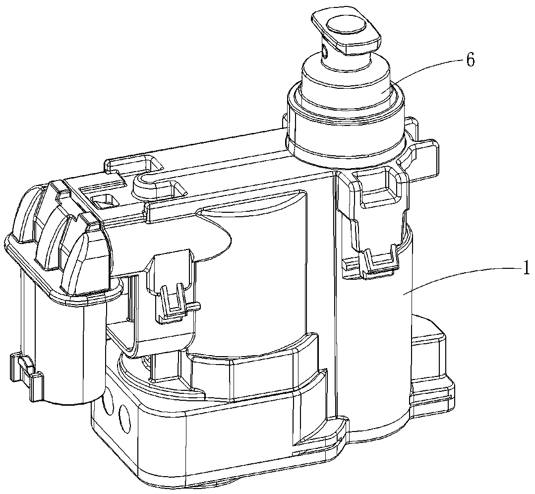
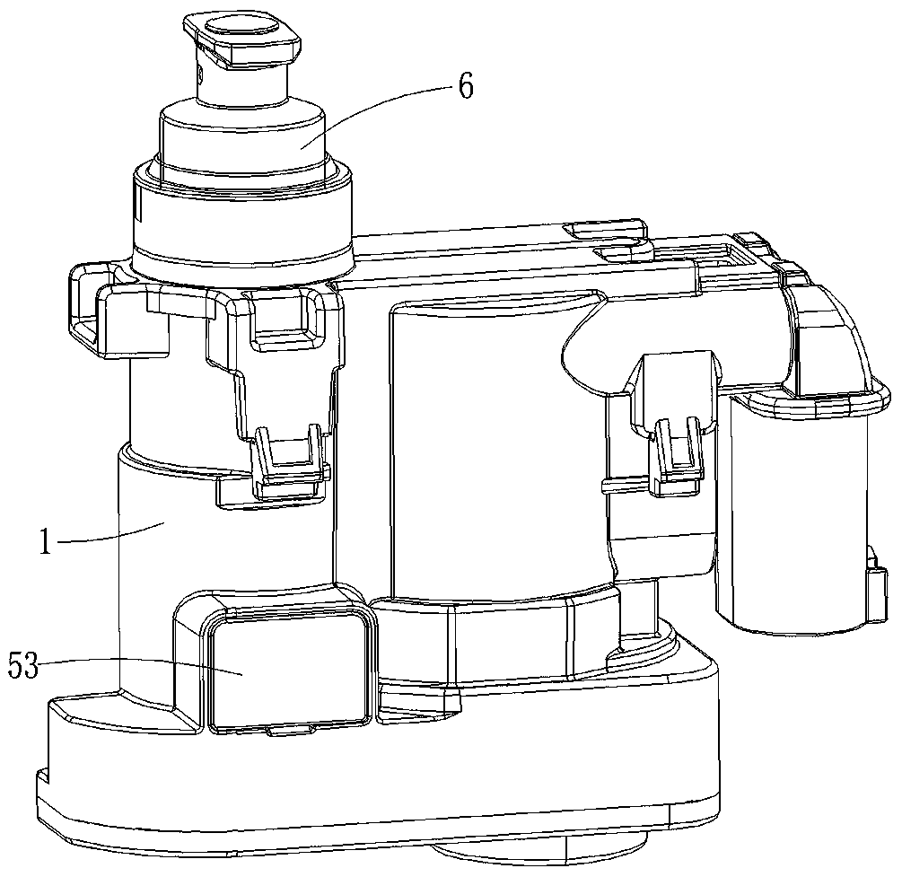
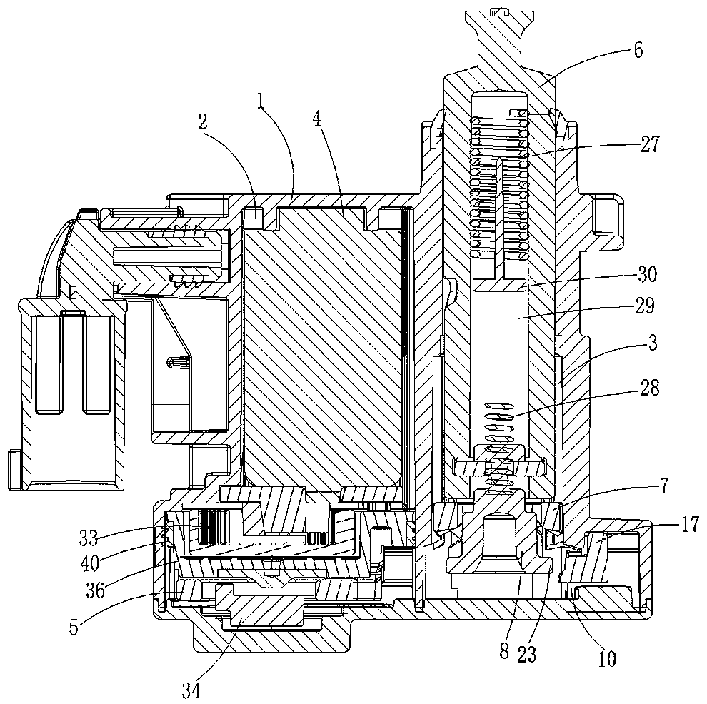
[0043] refer to Figure 1 to Figure 13 , a vehicle micro-actuator applied to the fuel tank cover or charging box cover of an automobile, comprising a housing 1, the housing 1 is divided into a motor cavity 2 and a locking cavity 3, and the motor cavity 2 is provided with An electric locking assembly, the electric locking assembly includes a motor 4, a transmission assembly and a locking member 5 from top to bottom, the motor 4 communicates with the vehicle electronic control system, and the locking chamber 3 A manual locking assembly is provided, and the manual locking assembly includes a rotary push rod 6, a drive sleeve 7 and a rotary sleeve 8 from top to bottom, and the rotary push rod 6 is connected to the car cover in transmission, and the The electric locking assembly can lock the manual locking assembly, and the locking member...


PUM


Abstract

A vehicle microactuator applied to a refueling tank cover or a charging box cover of a vehicle comprises a casing divided into a motor cavity and a lockup cavity, wherein an electric locking assemblyis arranged in the motor cavity and sequentially comprises a motor, a drive assembly and a locking part from top to bottom, a manual locking assembly is arranged in the lockup cavity and sequentiallycomprises a rotary push rod, a driving sleeve and a rotating sleeve from top to bottom, the locking part comprises a locking base part located in the motor cavity, a locking tongue for locking the rotating sleeve and a hook arm used for connecting the locking base part and the locking tongue, a passage matched with the hook arm is arranged between the motor cavity and the lockup cavity, a lockinghole is formed in the wall of the lockup cavity and communicated with the passage, and the locking tongue can penetrate through the lock hole and forms interference fit with the rotating sleeve. The rotating sleeve is a component located at the last link of the manual locking assembly, therefore, the mutual acting force between the locking tongue and the rotating sleeve is relatively smaller, andthe risk of part wear and breakage can be effectively reduced.

Description

technical field [0001] The invention relates to the technical field of auto parts, in particular to a micro-actuator for a vehicle applied to a fuel tank cover or a charging tank cover of an automobile. Background technique [0002] Nowadays, with the development of the automobile industry and the increase in the popularity of automobiles, people have higher and higher requirements for the performance of automobiles, and they also pay more attention to the speed, convenience and safety of various operations of vehicles. Therefore, automobile companies It is especially important for the improvement of vehicle structure and the application of new technologies. [0003] In the traditional structure, for the opening and closing of the small door of the fuel filler cap or the small door of the charging port cover, most of them are unlocked or locked mechanically, that is, the lock lever is fixed on the small door, and the lock sleeve is fixed on the body seat. Or pull the cable ...

Claims


Application Information

Patent Timeline
Patent Type & Authority Applications(China)
IPC IPC(8): E05B83/28E05B77/34E05B81/06E05B81/16E05B83/34E05B85/00
CPCE05B83/28E05B81/06E05B77/34E05B81/16E05B85/00E05B83/34Y02T90/14E05B81/28E05B81/30B60K15/05E05B81/44
Inventor 孙云飞周君臣
Owner NINGBO HUAKAI ELECTRONICS TECH CO LTD
Why Eureka
Try Eureka