Multifunctional efficient cleaning basin

A multi-functional and high-efficiency technology, used in wellbore/well components, earth-moving, construction, etc., to solve problems such as sand, cement, and milling debris easily re-inhaled into the well, and the pool has no partitions.

Pending Publication Date: 2020-04-28
潘红涛
View PDF0 Cites 0 Cited by
  • Summary
  • Abstract
  • Description
  • Claims
  • Application Information

AI Technical Summary

Problems solved by technology

[0003] The cleaning pool used in downhole operations has the problem that there is no partition in the middle of the pool during drilling, punching and milling, and the sand, cement, and milling debris washed out of the well are easily sucked into the well again.

Method used


Image

  • Multifunctional efficient cleaning basin

Examples


Embodiment 1

[0029] An oil field refers to a specific area where crude oil is produced, while an oil field well site refers to the flat field in front of the drilling platform, which is used to discharge drill pipes and casings, park cement trucks during well cementing, and park logging vehicles during well logging, etc. The length of the well site The size and area should ensure that when the drilling equipment is installed, the derrick can be leveled and various drilling equipment, hoisting machinery and vehicles can be parked and turned.

[0030] The cleaning pool used in downhole operations has the problem that there is no partition in the middle of the pool during drilling, punching and milling, and the sand, cement, and milling debris washed out of the well are easily sucked into the well again.

[0031] Therefore, aiming at the above problems, the present invention provides a multi-functional and high-efficiency cleaning pool.

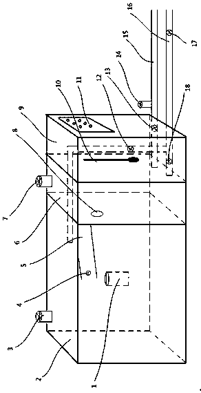
[0032] Specific as figure 1 As shown, a multifunction...

Embodiment 2

[0044] The embodiment of the present invention is further limited on the basis of embodiment 1.

[0045] see figure 1 A diversion tank 5 is installed inside the sedimentation tank 2 at the junction of the sedimentation tank 2 and the overflow circulation tank 6, and a magnet 4 is arranged inside the diversion tank 5, and is arranged inside the sedimentation tank 2 at the lower end of the outlet of the diversion tank 5 There is a sampling barrel 1 .

[0046] The diversion groove 5 is arranged in an inclined shape near the end of the overflow circulation pool 6 .

[0047] The sand-carrying fluid returned from drilling, punching, milling and milling flows into the diversion tank 5 through the blowout pipeline 16, and the magnet 4 arranged inside the diversion tank 5 and the sampling bucket 1 provided below the outlet cooperate with each other to realize The return matter in the well can flow into the sampling barrel 1 for sampling. If there is iron-containing substance in the r...


PUM


Abstract

The invention particularly relates to a multifunctional efficient cleaning basin, and belongs to the field of borehole operation equipment. The multifunctional efficient cleaning basin comprises a sedimentation basin and an overflow circulating basin which are arranged side by side, the sedimentation basin communicates with the overflow circulating basin through a communication hole, and the communication hole is formed in the upper half part of the basin wall between the sedimentation basin and the overflow circulating basin; a sewage pipe is arranged at the bottom of the overflow circulatingbasin in a communicating mode, and relief pipelines are arranged on the side of the sewage pipe side by side; the relief pipelines are formed by bent pipes and horizontal pipes which communicate witheach other, the inner ends of the horizontal pipes communicate into the overflow circulating basin, a gate II is mounted at the position, close to the horizontal pipe of one side of the overflow circulating basin, at the joint of the bent pipe and the horizontal pipe, and a gate I is mounted on the horizontal pipe on the other side; the bent pipe penetrates through the top of the overflow circulating basin and communicates with the sedimentation basin, and a gate IV is mounted on the bent pipe. The multifunctional efficient cleaning basin has functions of circulating, sand setting, discharging and overflowing sewage, limiting and protecting, pumping water and sampling.

Description

technical field [0001] The invention relates to the field of downhole operation equipment, in particular to a multifunctional and efficient cleaning pool. Background technique [0002] An oil field refers to a specific area where crude oil is produced, while an oil field well site refers to the flat field in front of the drilling platform, which is used to discharge drill pipes and casings, park cement trucks during well cementing, and park logging vehicles during well logging, etc. The length of the well site The size and area should ensure that when the drilling equipment is installed, the derrick can be leveled and various drilling equipment, hoisting machinery and vehicles can be parked and turned. [0003] The cleaning pool used in downhole operations has the problem that there is no partition in the middle of the pool during drilling, punching and milling, and the sand, cement, and milling debris washed out of the well are easily sucked into the well again. [0004] T...

Claims


Application Information

Patent Timeline
IPC IPC(8): E21B21/01E21B41/00
CPCE21B21/01E21B41/005
Inventor 潘红涛窦彦辉弓家坤南庆果石佃鹏潘永光董海玲陈瑞娟段海珊陈新兵潘华民
Owner 潘红涛
Why Eureka
Try Eureka