Method for checkinkg temp. sensor and device for controlling transfer torque in motor-driven vehicle

A temperature sensor, motor vehicle technology, applied in the direction of control devices, transportation and packaging, couplings, etc., can solve the problems of pressure loss that cannot be compensated by the return spring, functional failure, etc., and achieve the effect of high clutch operation safety

Inactive Publication Date: 2004-07-28
LUK GETRIEBE SYST
View PDF1 Cites 0 Cited by
  • Summary
  • Abstract
  • Description
  • Claims
  • Application Information

AI Technical Summary

Problems solved by technology

At low temperatures there is a danger that this pressure loss cannot be compensated by the return spring, so that a negative pressure is generated in the working chamber of the delivery cylinder, which leads to a hydraulic system consisting of two working chambers and corresponding pipes self-pumping
This can lead to serious functional failures

Method used


Image

  • Method for checkinkg temp. sensor and device for controlling transfer torque in motor-driven vehicle
  • Method for checkinkg temp. sensor and device for controlling transfer torque in motor-driven vehicle
  • Method for checkinkg temp. sensor and device for controlling transfer torque in motor-driven vehicle

Examples


Embodiment Construction

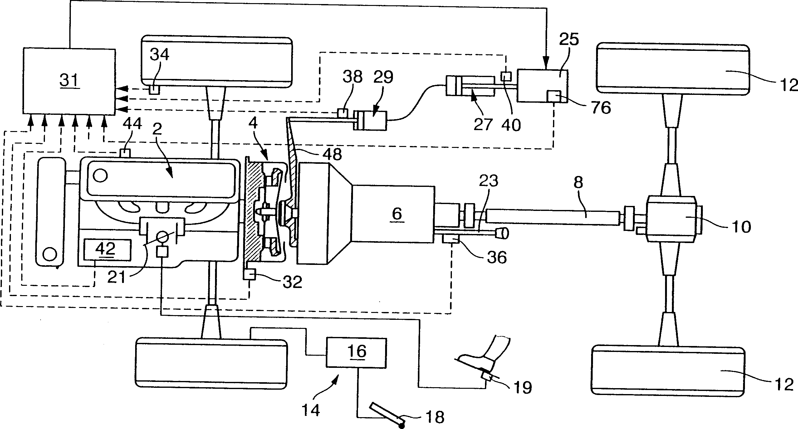
[0027] according to figure 1 , a motor vehicle has an engine, such as an internal combustion engine 2, which is connected via a clutch 4 to a transmission, such as a shift gearbox 6, which drives the rear wheels 12 via a cardan shaft 8 and a differential 10. For braking the motor vehicle, a brake device 14 is provided with a brake mechanism 16 which is actuated via a brake pedal 18 . Only the connection from the brake mechanism 16 to the left front wheel has been described here. It can be understood that the braking mechanism 16 cooperates with all the wheels of the motor vehicle.

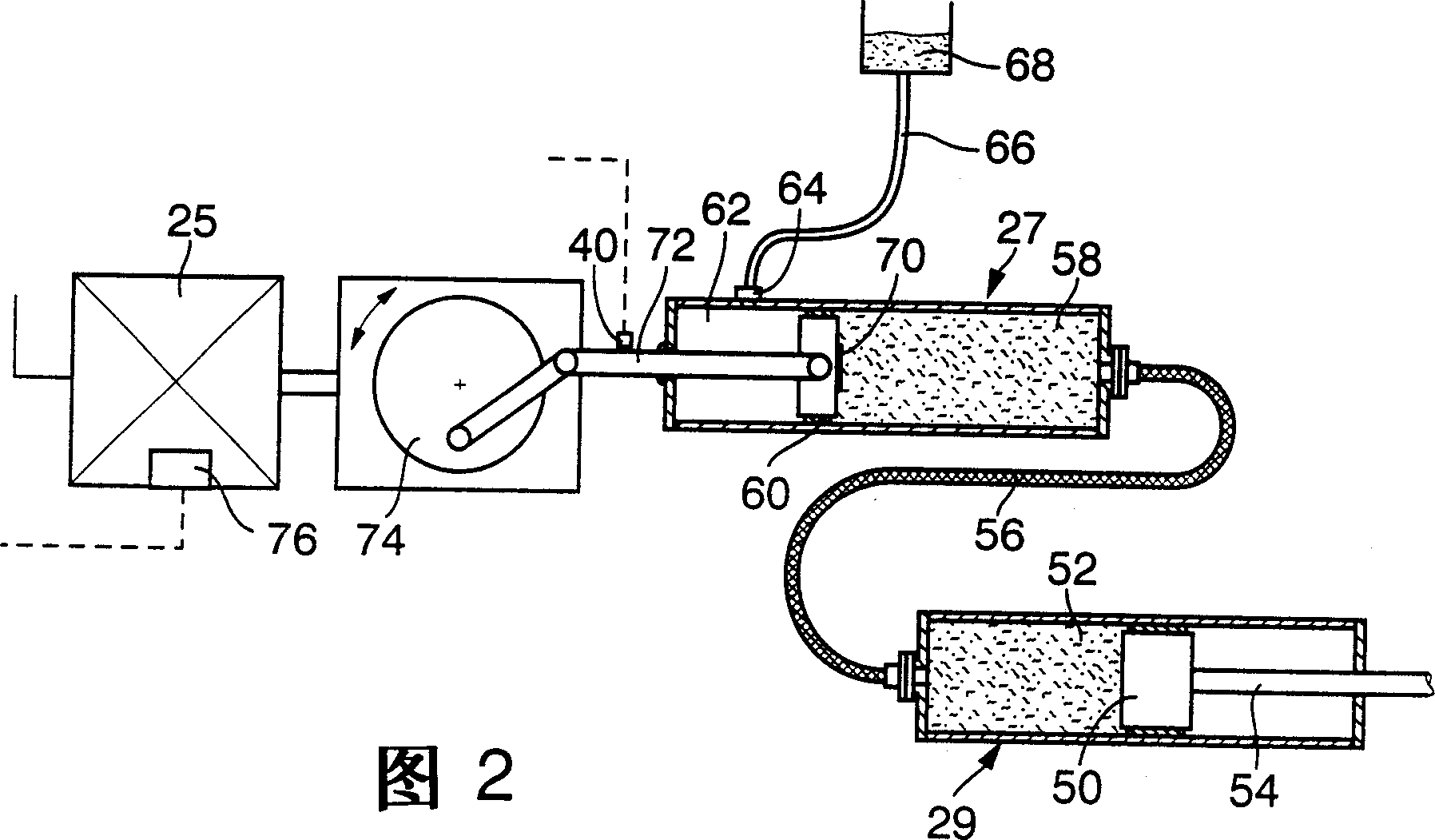
[0028]To control the load on internal combustion engine 2 , a driver pedal 19 is provided, which actuates a throttle valve 21 . The gearbox 6 is shifted by means of a selector lever 23 . The clutch 4 is set automatically and is actuated by an operating unit such as a reactor 25 via a sending cylinder 27 and a receiving cylinder 29 . The reactor 25 is controlled by a control unit such as an elec...


PUM


Abstract

The clutch is incorporated in the vehicle transmission system, the master-cylinder piston being moved by an actuator with the movement transmitted hydraulically by pipe to a slave-cylinder piston. The latter disengages the clutch in opposition to a return spring, while the master cylinder piston contains a non-return valve allowing fluid transfer from a compensating chamber to the master-cylinder working chamber. The actuator is so controlled that even at low temperatures movement of the master cylinder piston in the direction increasing the volume of the master-cylinder working chamber (27) the pressure generated by the return spring in this chamber is maintained. During this movement no flow of fluid takes place from the working chamber to the compensating one. Fluid temperature can be measured or computed, and at low temperatures the speed of movement of the master-cylinder piston can be reduced.

Description

[0001] The present invention is a divisional application of No. 98102220.0 invention patent application with the title of "Method for Operating Automatic Clutch and Method for Detecting Temperature Sensor" submitted to the Chinese Patent Office on June 3, 1998. technical field [0002] The invention relates to a method for operating an automatic clutch placed in the transmission line of a motor vehicle; the invention also relates to a method for checking a temperature sensor placed in a reactor, and in particular a reactor of an automatic clutch Method; The invention also relates to a device for controlling the torque transmittable by an automatic clutch in the transmission line of a motor vehicle. Background technique [0003] So far, the clutch cooperation automation setting of the pedal operation in the motor vehicle has been gradually increased and popularized. On the one hand, such clutches bring about a significantly improved comfort, on the other hand, they are especi...

Claims


Application Information

Patent Timeline
Patent Type & Authority Applications(China)
IPC IPC(8): F16D28/00F16D29/00F16D48/02F16D48/06
CPCF16D29/005F16D48/064F16D2300/18F16D48/066F16D2500/1026F16D2500/10412F16D2500/30404F16D2500/3056F16D2500/3166F16D2500/70406F16D2500/7041F16D2500/70694
Inventor 阿尔方斯·瓦格纳扬·格拉本斯泰特尔托马斯·拉姆赫夫米夏埃尔·萨莱克尔
Owner LUK GETRIEBE SYST
Why Eureka
Try Eureka