Intelligent water injection instrument for oil field

An intelligent, oilfield technology, applied in isolation devices, production fluids, boreholes/well components, etc., can solve problems such as water injectors not working properly and unable to meet the requirements of use

Inactive Publication Date: 2020-04-28
XIAN INT INSTR MEASURE & CONTROL EQUIP
10 Cites 0 Cited by

AI-Extracted Technical Summary

Problems solved by technology

[0005] This application provides an intelligent water injection instrument for oilfields to solve the defect that the water injector cannot work normally due to the low tem...

Abstract

The invention provides an intelligent water injection instrument for an oil field. The intelligent water injection instrument comprises a water injection instrument main body, wherein the periphery ofthe water injection instrument main body is provided with a thermal insulation layer, a first temperature detector is arranged on the water injection instrument main body and located on the outer side of the thermal insulation layer, a second temperature detector is arranged on the water injection instrument main body and located on the inner side of the thermal insulation layer, a water injectorcontroller and temperature controller assembly and a first heater are also arranged on the water injection instrument main body in the thermal insulation layer, the first temperature detector, the second temperature detector, the water injector controller and temperature controller assembly and the first heater are connected with one another, the first temperature detector and the second temperature detector are used for detecting temperatures of environments inside and outside the thermal insulation layer and sending temperature data to the water injector controller and temperature controller assembly, and the water injector controller and temperature controller assembly is used for controlling the first heater to work, so that the temperature of the environment inside the thermal insulation layer is increased, and the problem that an existing intelligent water injection instrument for the oil field cannot operate at low temperature is solved.

Application Domain

ConstructionsInsulation +1

Technology Topic

Thermal insulationInjector +6

Image

  • Intelligent water injection instrument for oil field
  • Intelligent water injection instrument for oil field
  • Intelligent water injection instrument for oil field

Examples

  • Experimental program(1)

Example Embodiment

[0033] In order to enable those skilled in the art to better understand the technical solutions in this application, the following will clearly and completely describe the technical solutions in the application embodiments in conjunction with the drawings in the embodiments of this application; obviously, the described implementation The examples are only a part of the embodiments of the present application, rather than all the embodiments. Based on the embodiments in this application, all other embodiments obtained by those of ordinary skill in the art without creative work should fall within the protection scope of this application.
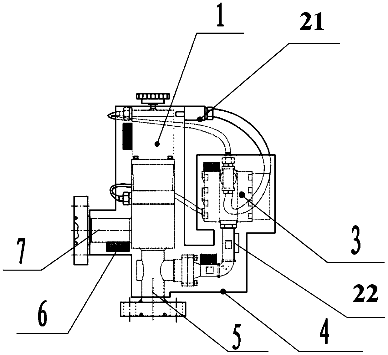
[0034] Please refer to the attached figure 1 , Attached figure 1 A schematic structural diagram of an oilfield intelligent water injection device provided by an embodiment of this application. As shown in the figure, an oilfield intelligent water injection device provided by an embodiment of this application includes a water injection device main body 1 with an insulation layer 4 on the periphery;
[0035] A first temperature detector 21 is provided on the main body 1 of the water injection instrument outside the insulation layer 4, and a second temperature detector 22 is installed on the main body 1 of the water injection instrument inside the insulation layer 4;
[0036] The main body 1 of the water injection device in the thermal insulation layer 4 is also provided with a water injection device controller and a temperature controller assembly 3 and a first heater 6, the first temperature detector 21, the second temperature detector 22, and the water injection device. The controller and the temperature controller assembly 3 and the first heater 6 are connected to each other; wherein the water injector controller and the temperature controller assembly 3 at least include a metering controller and a temperature controller integrated with the water injector, the first The temperature detector 21 and the second temperature detector 22 are screwed to the main body 1 of the water injection meter.
[0037] At the same time, the thermal insulation layer 4 is used to maintain the temperature of the environment where the water injection instrument main body 1 is located inside the thermal insulation layer 4, and reduce the attenuation range of the internal temperature of the thermal insulation layer 4;
[0038] The first temperature detector 21 is used to detect the temperature of the external environment of the insulation layer 4, and send the detected temperature data of the external environment to the water injector controller and the temperature controller assembly 3;
[0039] The first temperature detector 21 is used to detect the internal environmental temperature of the thermal insulation layer 4, and send the detected temperature data of the internal environment to the water injector controller and the temperature controller assembly 3;
[0040] The water injector controller and the temperature controller assembly 3 are used to receive the detection data of the internal and external environment of the thermal insulation layer 4, and compare the preset temperature data with the detection data of the internal and external environment, and report to the The first heater 6 sends an on or off instruction;
[0041] The first heater 6 is used to turn on or turn off according to the instruction.
[0042] The first temperature detector 21 and the second temperature detector 22 detect the ambient temperature inside and outside the insulation layer 4, and send the temperature data to the water injector controller and the temperature controller assembly 3, through the water injector controller and the temperature controller The component 3 controls the operation of the first heater 6 to increase the ambient temperature inside the thermal insulation layer 4, which solves the defect that the water injector cannot work normally due to the low temperature in the oilfield water injection process where the ambient temperature is low. The problem of being unable to meet the requirements for use in a lower temperature environment, the intelligent water injection instrument for oil fields provided in the embodiments of this application can be applied at least in an environment where the minimum temperature reaches or close to -40°C to ensure the effective progress of the oil field water injection process, and Existing products or technologies can only be realized within -20°C. When the temperature is low, normal measurement cannot be performed, and the liquid crystal cannot be displayed, controlled, and communicated normally, which cannot meet the requirements for use in a lower temperature environment.
[0043] When the intelligent water injection instrument for oil field provided in the embodiments of this application is used in the field, the temperature in the insulation layer 4 will be affected due to the change of environment temperature, and the temperature in the insulation layer 4 is too high or too low, and the water injection device cannot work normally , So it is necessary to set the upper and lower temperature limits to maintain the temperature in the insulation layer 4. Therefore, the operator sets the upper and lower temperature limits for the temperature controller in the water injector controller and temperature controller assembly 3 according to the actual temperature on site in advance, and sets the upper and lower temperature limits for the water injector controller and temperature controller assembly 3 according to the user. , Automatically adjust the temperature.
[0044] The temperature value of the external environment is collected by the first temperature detector 21, and the collected temperature value is fed back to the temperature controller in the water injector controller and the temperature controller assembly 3. When the outside temperature is lower than the lower temperature limit set in the temperature controller , The temperature controller sends an instruction to the first heater 6, and the first heater 6 starts to heat up rapidly in the full power mode. At this time, the first heater 6 quickly heats up and releases heat energy into the insulation layer 4. When the first heater 6 The temperature continues to increase until the temperature value collected by the second temperature detector 22 reaches the set temperature upper limit, the temperature controller controls the first heater 6 to reduce the heating power to 20% of the rated power, and the insulation layer 4 Reduce the temperature attenuation range, so that the smart water injector can work in the required temperature environment. When the temperature of the external environment continues to decrease and the temperature in the insulation layer 4 drops to the set temperature lower limit, the temperature controller controls the first heating again The device 6 works according to the above steps, so that the ambient temperature of the component mechanical part of the intelligent water injector controller is kept above 0°C, to ensure the normal metering and control of the meter, and to ensure that the water injector works normally within the required temperature.
[0045] Optionally, the water injector controller includes a metering sensor, a control valve, a control motor, a connecting pipeline, and a mounting flange arranged on the water injector main body 1, and also includes devices such as liquid crystal and electronic parts. , Control valves, control motors, connecting pipelines and mounting flanges or liquid crystal and electronic parts and other devices are at normal operating temperature, the smart water injector can work in a normal environment, which solves the oilfield water injection process with low on-site environmental temperature Among them, the defect that the water injector cannot work normally due to the low temperature, and the problem that it cannot meet the requirements for use in a lower temperature environment.
[0046] In addition to using the thermal insulation layer 4 for thermal insulation, in order to protect the liquid crystal and electronic parts that are most affected by temperature changes, in the water injector controller and temperature controller assembly 3, the water injector controller and temperature controller assembly 3 are also provided There is a third temperature detector and an infrared heating device; the third temperature detector and the infrared heating device are integrated on the control circuit board of the water injector controller and the temperature controller assembly 3, and the water injector controller And the single-chip control on the water injector controller in the temperature controller assembly 3;
[0047] The third temperature detector is used to detect the internal ambient temperature of the thermal insulation layer 4 and send the detected data to the single chip. The single chip microcomputer is the main processor of the smart water injector and is used to receive all the collected data. Data, and after calculation and judgment, a logic command is issued. The stand-alone chip is integrated on the control circuit board in the water injector controller and temperature controller assembly 3. When the stand-alone chip receives the external temperature conversion value is too low, it will send the infrared detection device instructions to perform temperature control;
[0048] The stand-alone chip is used to receive the internal environmental temperature of the thermal insulation layer 4, compare preset temperature data with the internal environmental temperature data, and send an on or off instruction to the infrared heating device according to the comparison result ;
[0049] The infrared heating device is used to turn on or turn off according to the instruction.
[0050] When the heating component in the insulation layer 4 fails or fails, the single-chip microcomputer controls the temperature in the insulation layer 4. When the temperature is too low, the single-chip microcomputer controls the infrared heating device in the component to work, so that the temperature in the component is higher than the preset temperature and the electronic part is normal When the heater in the thermal insulation layer 4 works normally, the single-chip microcomputer stops the infrared heating device inside the component according to the normal temperature indication and starts the energy-saving mode.
[0051] Optionally, a high-pressure filter device 8 is provided on the water inlet pipe 5 of the water injection instrument main body 1, and the high-pressure filter device 8 filters impurities in the measurement medium to prevent damage to the metering components, such as figure 2 As shown, when the measuring medium containing impurities enters the smart water injector from the water inlet pipe 5, it first passes through the filter part. After the medium is filtered by the filter part, it enters the smart water injector to prevent foreign matter from entering the smart water injector. Measurement accuracy
[0052] The outlet pipe 7 of the main body 1 of the water injection instrument is provided with a high-pressure one-way valve 9 to prevent water backflow. When the pressure of the water injection well is greater than the inlet pressure of the smart water injector, the sewage in the water injection well will flow back into the outlet pipe 7 of the smart water injector. In the water injector, it will damage the meter and affect the accuracy of measurement, such as image 3 Add a high pressure check valve 9 to the outlet pipe 7. When the inlet pressure is greater than the injection well pressure, the high pressure check valve 9 opens normally. When the injection well head pressure is greater than the water inlet pressure, the ball valve in the high pressure check valve 9 closes and the well head Backwater cannot flow back.
[0053] Optionally, the water injector controller and temperature controller assembly 3 is also connected to a remote terminal device through a communication module. The water injector controller and temperature controller assembly 3 transmits data to the communication module through the 485 interface. The data is transmitted and analyzed by auxiliary equipment such as servers, and remote data monitoring can be performed through remote terminal equipment such as mobile phones and PC mobile communication equipment.
[0054] Optionally, the first heater 6 is a temperature-adjustable heater, which can be selected and set according to actual needs.
[0055] The intelligent water injection instrument for oil field provided in this application adopts a humanized design, and the user can use it flexibly according to the actual temperature on the spot. The upper and lower temperature limits and the water injector control can be set remotely, without the need for personnel to go back and forth on-site operation, and the water injector control The heater and temperature controller assembly 3 can also turn on or off the two heating functions of the first heater 6 and the infrared heating device according to temperature changes. When the external temperature rises in summer, turn off the first heater 6 and the infrared heating device to reduce Use energy consumption.
[0056] It should be noted that relational terms such as "first" and "second" are only used to distinguish one entity or operation from another entity or operation, and do not necessarily require or imply any of these entities or operations. There is any such actual relationship or order between. Moreover, the terms "including", "including" or any other variation thereof are intended to cover non-exclusive inclusion, so that an article or device including a series of elements includes not only those elements, but also other elements that are not explicitly listed. Or it also includes elements inherent to such a process, method, article, or equipment. If there are no more restrictions, the element defined by the sentence "including a..." does not exclude the existence of other same elements in the process, method, article, or equipment including the element.
[0057] The above are only specific implementations of the application, so that those skilled in the art can understand or implement the application. Various modifications to these embodiments will be obvious to those skilled in the art, and the general principles defined herein can be implemented in other embodiments without departing from the spirit or scope of the application. Therefore, this application will not be limited to the embodiments shown in this text, but should conform to the widest scope consistent with the principles and novel features disclosed in this text.
[0058] It should be understood that this application is not limited to what has been described above and shown in the drawings, and various modifications and changes can be made without departing from its scope. The scope of the application is only limited by the appended claims.

PUM

no PUM

Description & Claims & Application Information

We can also present the details of the Description, Claims and Application information to help users get a comprehensive understanding of the technical details of the patent, such as background art, summary of invention, brief description of drawings, description of embodiments, and other original content. On the other hand, users can also determine the specific scope of protection of the technology through the list of claims; as well as understand the changes in the life cycle of the technology with the presentation of the patent timeline. Login to view more.
Why Eureka
Try Eureka