Dual-mode system soil-removal gate

A dual-mode system and gate technology, which is applied in the direction of earth drilling, mining equipment, tunnels, etc., can solve the problems of muck stuck, muddy water gushing, not easy to jam the soil discharge gate, etc., achieve long service life, and solve muddy water gushing Effect

Inactive Publication Date: 2020-04-28
ANHUI TONGDU FLOW TECH
View PDF8 Cites 2 Cited by
  • Summary
  • Abstract
  • Description
  • Claims
  • Application Information

AI Technical Summary

Problems solved by technology

[0002] The cutter head of the shield machine is advanced, and the muck, stones, and muddy water excavated by the cutter head are continuously conveyed to the shield chamber by the screw conveyor and discharged by the discharge gate. At present, the discharge gate of the shield machine is a single gate , The discharge gate often encounters the phenomenon of muck stuck during work or muddy water gushing in places with a lot of water gushing; the rear end of the screw conveyor must be installed with a discharge gate for soil discharge, so we provide a dual-mode system discharge gate , to prevent muddy water gushing, the amount of soil can be adjusted to achieve soil plugging effect, and it is not easy to jam the high-performance dual-mode system soil discharge gate

Method used


Image

  • Dual-mode system soil-removal gate
  • Dual-mode system soil-removal gate
  • Dual-mode system soil-removal gate

Examples


Embodiment Construction

[0015] The following will clearly and completely describe the technical solutions in the embodiments of the present invention with reference to the accompanying drawings in the embodiments of the present invention. Obviously, the described embodiments are only some, not all, embodiments of the present invention. Based on the embodiments of the present invention, all other embodiments obtained by persons of ordinary skill in the art without making creative efforts belong to the protection scope of the present invention.

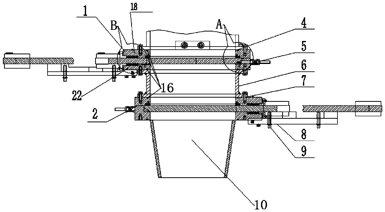
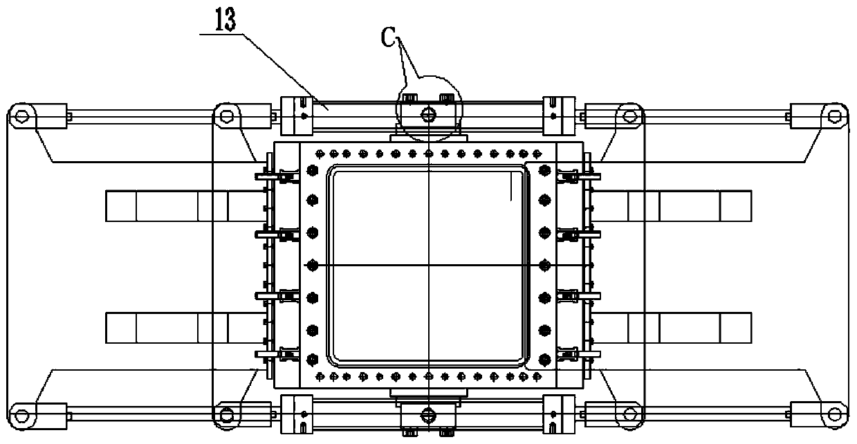
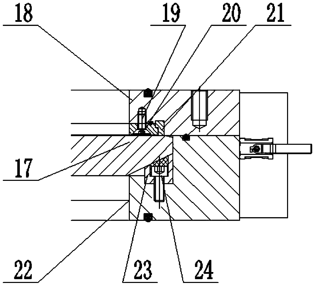
[0016] see Figure 1-5 , the present invention provides a technical solution: a dual-mode system soil discharge gate, including an upper valve body 18, a lower valve body 22, a hydraulic actuator 13 and a gate, and the gate includes a first gate 2 and a second gate 1. The first gate 2 is installed on the lower end of the capacity sleeve 6, the hydraulic actuator 13 is installed on both sides of the first gate 2, the second discharge gate 1 is installed on the ...


PUM


Abstract

The invention discloses a dual-mode system soil-removal gate which comprises an upper valve body, a lower valve body, a first gate and a second gate. The first gate is arranged at the lower end of a capacity sleeve pipe; hydraulic actuators are arranged on two sides of the first gate; the second soil-removal gate is arranged at the upper end of the capacity sleeve pipe; flushing devices are arranged on two sides of the first gate and the second gate; a groove is formed in the connected part of the lower valve body and a flashboard; a copper wedge block is arranged in the groove and is fixed into the groove through a screw; an eleven-degree oblique angle matched with the copper wedge block is arranged at the tail end of the flashboard; a T-shaped groove is formed in the connecting part of the upper valve body and the flashboard; a rectangular copper bar is arranged in the groove and is abutted against a rectangular tetrafluorohydrazine sealing block; and the rectangular tetrafluorohydrazine sealing block is connected with the upper valve body through an adjusting bolt. According to the mode system soil-removal gate for a shield tunneling machine, the first soil-removal gate, the second soil-removal gate and the capacity sleeve pipe are combined for removing soil and discharging muddy water, so that the problem that the muddy water is spouted is effectively solved, a high-efficient water stopping performance is realized, muck is not easy to accumulate, the service life is long, and the soil removal amount can be adjusted at any time so as to realize a soil plug effect.

Description

technical field [0001] The invention relates to a soil discharge gate of a dual-mode system. Background technique [0002] The cutter head of the shield machine is advanced, and the muck, stones, and muddy water excavated by the cutter head are continuously conveyed to the shield chamber by the screw conveyor and discharged by the discharge gate. At present, the discharge gate of the shield machine is a single gate , The discharge gate often encounters the phenomenon of muck stuck during work or muddy water gushing in places with a lot of water gushing; the rear end of the screw conveyor must be installed with a discharge gate for soil discharge, so we provide a dual-mode system discharge gate , to prevent muddy water gushing, the amount of soil can be adjusted to achieve soil plugging effect, and it is not easy to block the high-performance dual-mode system soil discharge gate. Contents of the invention [0003] The object of the present invention is to provide a dual-mo...

Claims


Application Information

Patent Timeline
Patent Type & Authority Applications(China)
IPC IPC(8): E21D9/06E21D9/13
CPCE21D9/06E21D9/13
Inventor 陈磊王春汪小峰李文东巩文彬
Owner ANHUI TONGDU FLOW TECH
Why Eureka
Try Eureka