Anti-surge system and control method for screw conveyor

A screw conveyor and gushing prevention technology, which is applied in the direction of earth drilling, mining equipment, tunnels, etc., can solve the problem that the roadheader cannot continue to excavate the soil cabin, and achieve the effect of improving the tunnel construction environment, solving gushing, and preventing mud from settling

Active Publication Date: 2022-03-25
CHINA RAILWAY ENGINEERING EQUIPMENT GROUP CO LTD
View PDF11 Cites 0 Cited by
  • Summary
  • Abstract
  • Description
  • Claims
  • Application Information

AI Technical Summary

Problems solved by technology

[0009] In view of the deficiencies in the above-mentioned background technology, the present invention proposes a screw conveyor anti-spray system and its control method, which solves the problem that the existing screw conveyor anti-spray technology cannot keep the roadheader from continuing to advance and ensure Technical Problems of Stability of Soil Tank Pressure

Method used


Image

  • Anti-surge system and control method for screw conveyor
  • Anti-surge system and control method for screw conveyor
  • Anti-surge system and control method for screw conveyor

Examples


Embodiment 1

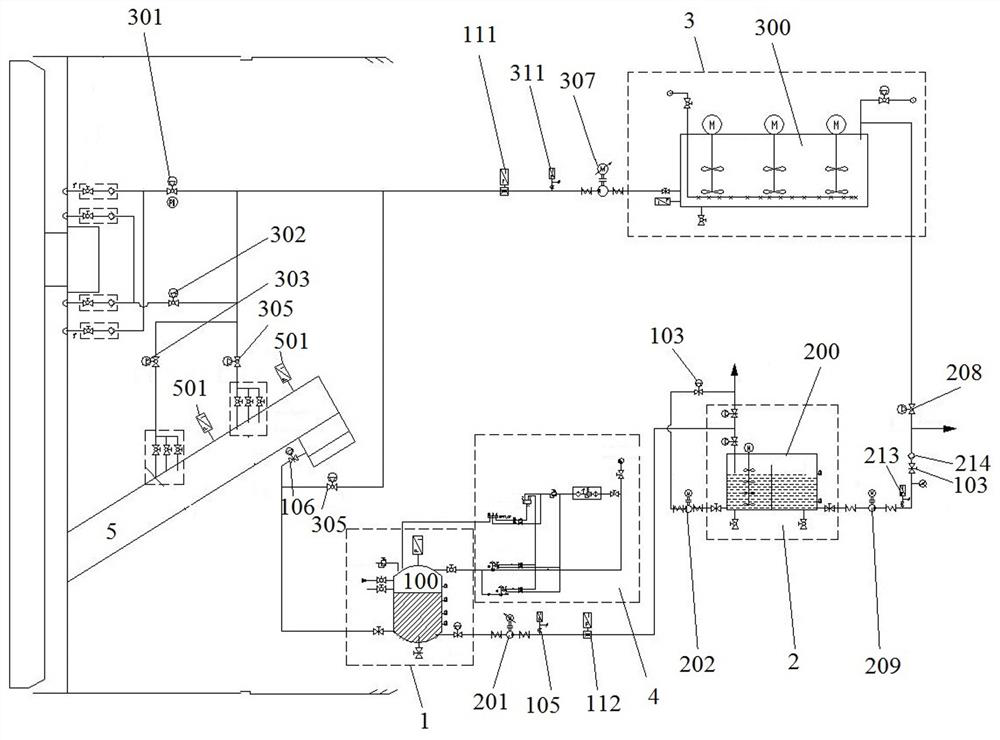
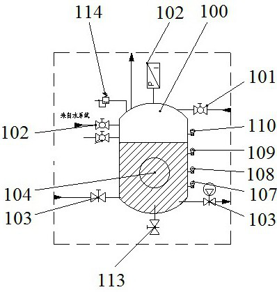
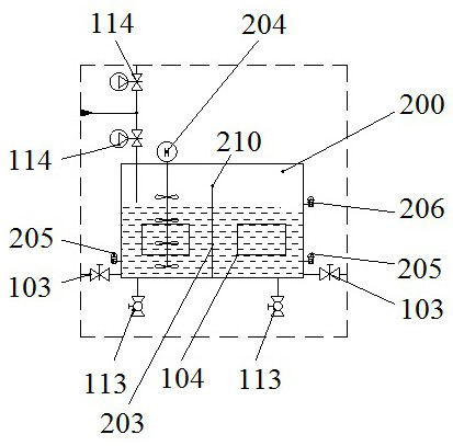
[0037] Embodiment 1, a kind of screw conveyor anti-splash system, such as figure 1 As shown, it is connected to the screw conveyor 5, and two first pressure sensors 501 are arranged at intervals in the axial direction of the screw conveyor 5 for detecting the pressure near the slag inlet and the slag outlet of the screw conveyor 5 . The screw conveyor 5 is provided with a grouting port and a grouting port, and a pressure holding unit 1, a slurry separation unit 2 and a mud improvement unit 3 are sequentially connected between the grouting port and the grouting port, and the pressure holding unit 1 includes a A second pressure sensor 102 is provided in the pressure holding tank 100 connected to the slurry discharge port, and the second pressure sensor 102 is connected to the pressure adjustment unit 4; the slurry separation unit 2 includes a slurry separation tank 200 connected to the pressure holding tank 100 , the mud tank of the slurry separation tank 200 is connected with t...

Embodiment 2

[0049] Embodiment 2, a control method for the anti-splashing system of a screw conveyor. During the tunneling process of the roadheader, when the screw conveyor 5 spews, the rear gate of the screw conveyor 5 is quickly closed, the propulsion is stopped, and the first control valve is opened. 301, the second control valve 302, start the slurry inlet pump 307, inject slurry into the soil cabin and the screw conveyor 5, keep the cutter head and the screw conveyor 5 rotating at a low speed, so that the particles and slurry in the muck are integrated and formed better ground fluidity; when the pressure measured by the first pressure sensor 501 at the front of the screw conveyor 5 is equivalent to the pressure of the first pressure sensor 501 in the middle, the first control valve 301 and the second control valve 302 are closed.

[0050] Start the pressure holding unit 1, set the pressure in the pressure holding tank 100 slightly lower than the pressure at the rear of the screw conve...


PUM


Abstract

The invention discloses an anti-splash system for a screw conveyor and a control method thereof. It is connected with the screw conveyor. The screw conveyor is provided with a first pressure sensor. The screw conveyor is connected with a pressure maintaining unit, a slurry separation unit and a slurry improvement unit. unit, the pressure holding unit includes a pressure holding tank connected to the slurry discharge port and is connected with a pressure adjustment unit, the slurry separation unit includes a slurry separation tank connected to the pressure holding tank, the mud pool of the slurry separation tank and the improved mud tank and drainage The mud improvement unit includes an improved mud tank, and the output end of the improved mud tank is connected in parallel with a slurry replenishment pipeline leading to the soil tank, the grouting port and the pressure holding tank. The invention can stabilize the pressure of the soil chamber at the set value when the tunneling machine gushes, and at the same time transport the dregs during the excavation process to the dregs truck or discharge them out of the tunnel, solve the problem of gushing without affecting the excavation of equipment, and improve the tunnel construction environment .

Description

technical field [0001] The invention relates to the technical field of screw machine slag discharge construction, in particular to a screw conveyor anti-splash system and a control method thereof. Background technique [0002] During shield tunneling construction, geological conditions, hydrological conditions, and tunneling parameters are the decisive factors for gushing. When the passage of groundwater in water-rich formations such as sand and pebbles is not blocked, or when additives such as foam and bentonite are used improperly, the improvement of dregs is not ideal, and the permeability of dregs cannot be effectively changed. In the case of large water flow or large hydraulic gradient Under normal circumstances, the screw machine of the roadheader is prone to gushing; in moderately weathered or slightly weathered rock formations, if the crack water develops and the rear waterway is not closed, due to the influence of flowing water, the muck in the excavation cabin of t...

Claims


Application Information

Patent Timeline
Patent Type & Authority Patents(China)
IPC IPC(8): E21D9/12E21D9/06
CPCE21D9/124E21D9/0642
Inventor 赵康峰赵云辉赵石徐智良俞培德周小磊李光张龙飞郭志勇蔡留金
Owner CHINA RAILWAY ENGINEERING EQUIPMENT GROUP CO LTD
Why Eureka
Try Eureka