Control method of dehumidification system

A control method and technology for dehumidifiers, which are applied in separation methods, air conditioning systems, and control inputs involving air characteristics, etc., can solve problems such as poor integration, complex structure, and inability to connect air-conditioning indoor units, reducing equipment costs and simplifying control. , the effect of simple structure

Inactive Publication Date: 2020-04-28
DAIKIN IND LTD
View PDF16 Cites 4 Cited by
  • Summary
  • Abstract
  • Description
  • Claims
  • Application Information

AI Technical Summary

Problems solved by technology

Moreover, due to the different functions of the heat exchanger (acting as a condenser or as an evaporator) during cooling and heating, in this compression cooling-adsorption dehumidification wheel coupling operation dehumidification device, it can only be used with only refrigeration function It cannot be connected to the cooling system with cooling and heating functions at the same time.
[0009] Furthermore, in this dehumidification device for coupled operation of compression refrigeration-adsorption dehumidification wheels, it is necessary to set up a processing fan (that is, a fan f

Method used


Image

  • Control method of dehumidification system
  • Control method of dehumidification system
  • Control method of dehumidification system

Examples


Embodiment Construction

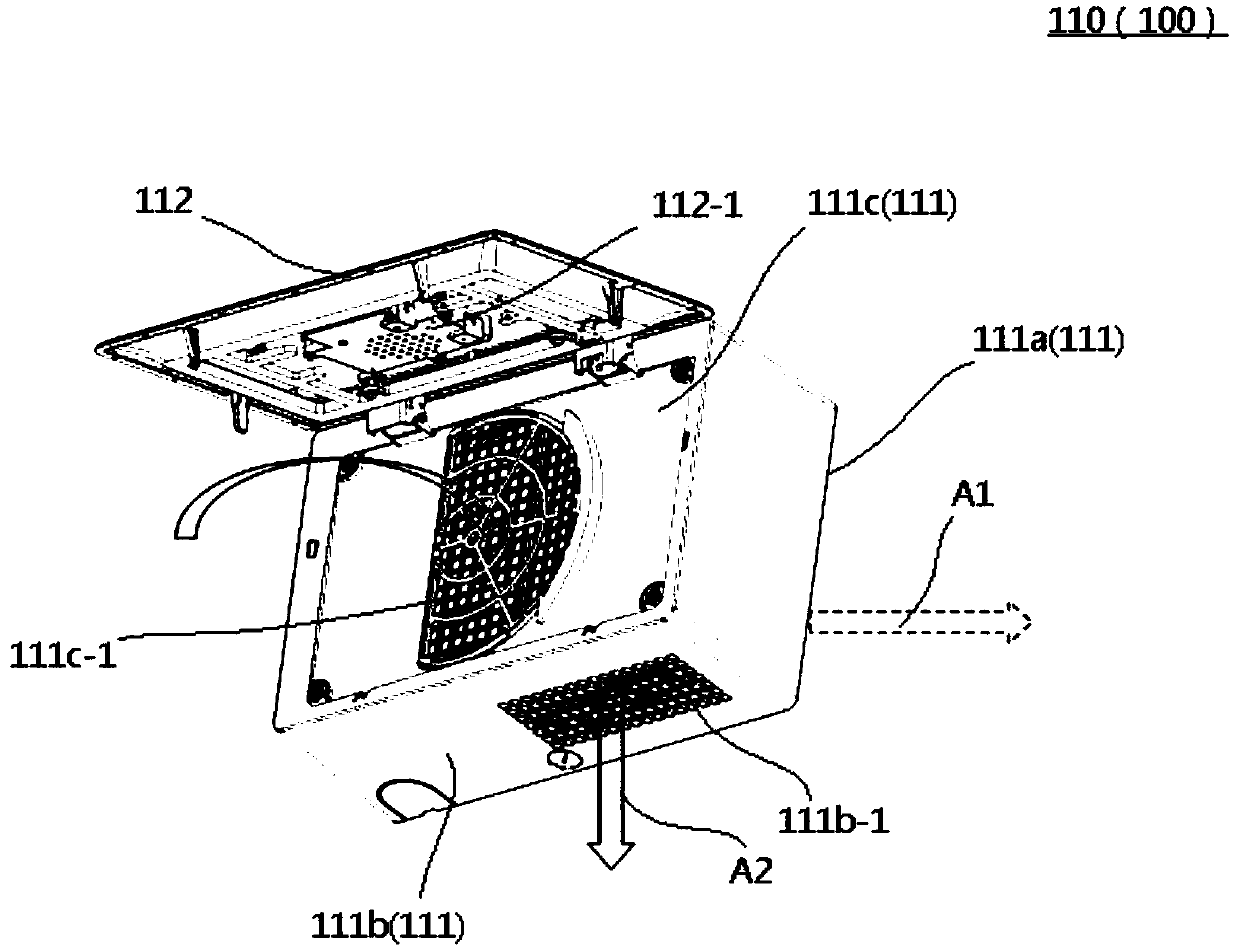
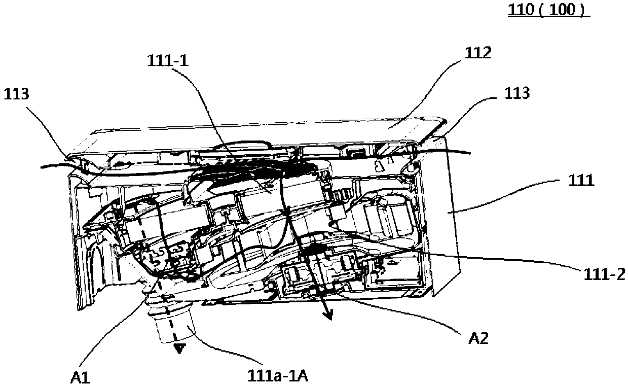
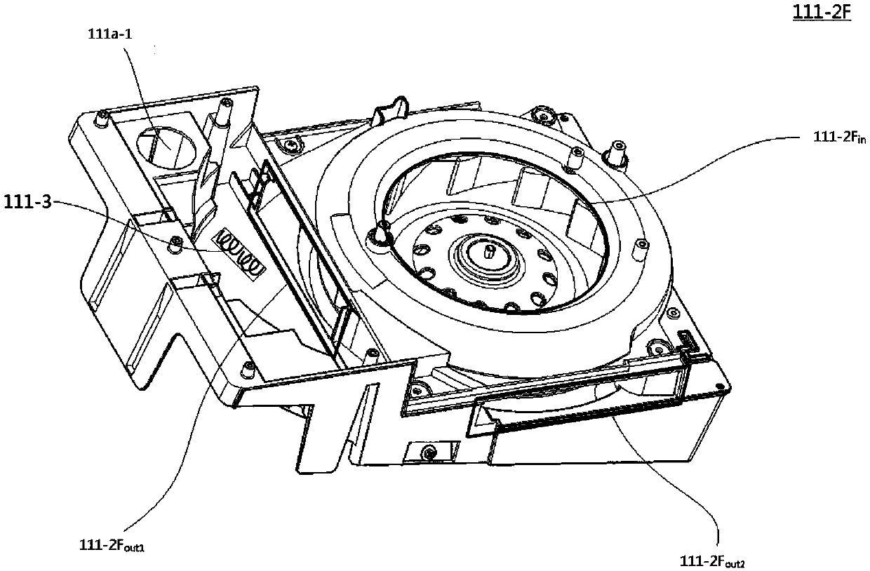
[0085] Below, refer to Figure 1 to Figure 3 , the dehumidifier 110 in the dehumidification system 100 according to one embodiment of the present invention will be described. figure 1 is a schematic perspective view schematically showing the internal structure of the dehumidifier 110 in the dehumidification system 100 according to one embodiment of the present invention, figure 2 is a schematic perspective view schematically showing the flow of air inside the dehumidifier 110 in the dehumidification system 100 according to one embodiment of the present invention, image 3 It is a schematic diagram which schematically shows the fan motor unit 111-2 and the heating unit 111-3 used in the dehumidifier 110 in the dehumidification system 100 which concerns on one embodiment of this invention.

[0086] The dehumidification system 100 of the present invention is, for example, a wall-mounted dehumidification system hung on an indoor wall, which includes a dehumidifier 110 , an air ...


PUM


Abstract

The invention provides a control method of a dehumidification system. Indoor air can be conditioned/purified through the exhaust function of the dehumidification system. The dehumidification system (100) comprises a dehumidifier (110) and a sensor detection device. The sensor detection device at least can detect the relative humidity and quality of the indoor air. The dehumidifier (110) can execute a dehumidification mode and an exhaust mode and execute at least one of an internal circulation mode, a standby mode and a shutdown mode. According to the control method of the dehumidification system (100), when the relative humidify value of the indoor air is greater than a preset humidity value, the dehumidifier (110) executes the dehumidification mode to condition the humidity of the indoorair; and when the relative humidity value of the indoor air is less than the preset humidity value, the dehumidifier (110) executes one of the exhaust mode, the internal circulation mode, the standbymode and the shutdown mode.

Description

technical field [0001] The invention relates to an air treatment system, and more particularly to a control method for a dehumidification system. Background technique [0002] In the past, as an air treatment system that regulates the temperature and humidity in the air (such as dehumidification systems such as dehumidifiers and dryers), there is known a compression refrigeration-adsorption dehumidification wheel coupling operation dehumidification device disclosed in the Chinese utility model patent announcement CN203771596U . [0003] In CN203771596U, the compression refrigeration-adsorption dehumidification runner coupling operation dehumidification device includes connecting at least one refrigeration system and an adsorption dehumidification runner system through pipelines. [0004] The refrigeration system mentioned above is Figure 6 As shown, the closed circuit composed of the refrigeration compressor (9), the pre-stage condenser (13), the rear-stage condenser (11),...

Claims


Application Information

Patent Timeline
IPC IPC(8): F24F11/64F24F11/65F24F110/20F24F110/10F24F110/50F24F120/10
CPCF24F11/64F24F11/65F24F2110/20F24F2110/10F24F2110/50F24F2120/10F24F3/14B01D53/26
Inventor 丁佳明张菁刘丽
Owner DAIKIN IND LTD
Why Eureka
Try Eureka