Ion implanter cleaning method

An ion implanter and ion implantation technology, applied in the direction of circuits, discharge tubes, electrical components, etc., can solve problems such as difficulty in meeting cleaning requirements, and achieve the effect of avoiding residue and accelerating discharge

Active Publication Date: 2020-04-28
HUA HONG SEMICON WUXI LTD
View PDF5 Cites 0 Cited by
  • Summary
  • Abstract
  • Description
  • Claims
  • Application Information

AI Technical Summary

Problems solved by technology

[0005] The invention provides a cleaning method for an ion implanter, which can solve the problem that related technologies are difficult to adapt to the cleaning requirements in various ion implantation processes

Method used


Image

  • Ion implanter cleaning method
  • Ion implanter cleaning method
  • Ion implanter cleaning method

Examples


Embodiment 1

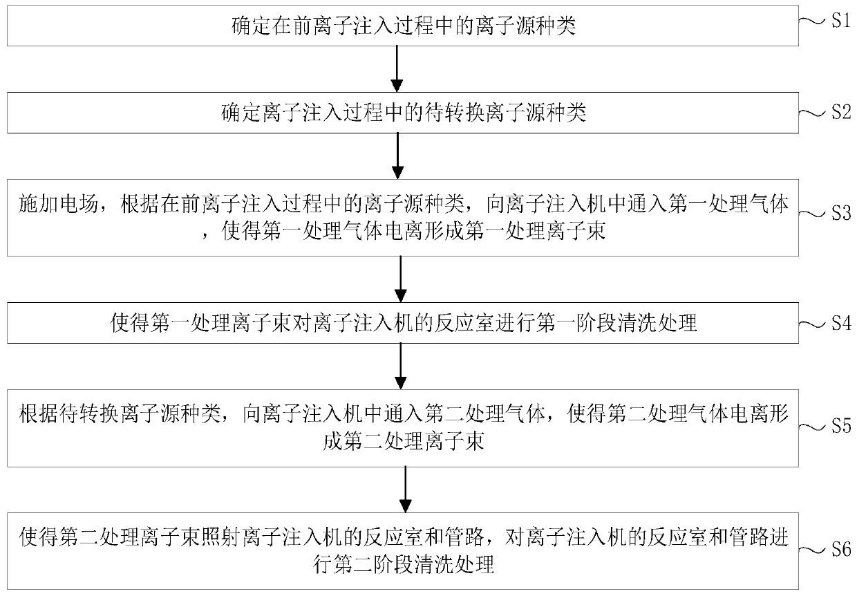
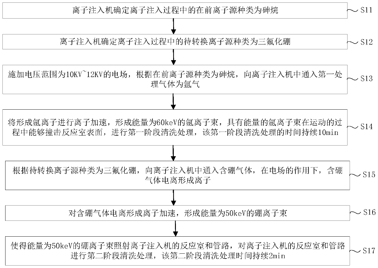
[0055] This embodiment provides a cleaning method for an ion implanter, referring to figure 2 , taking the former ion source as arsine and the ion source to be converted as boron trifluoride as an example.

[0056] S11: the ion implanter determines that the type of the previous ion source in the ion implantation process is arsine (AsH3);

[0057] S12: The ion implanter determines that the ion source to be converted during the ion implantation process is boron trifluoride (BF3);

[0058] S13: Apply an electric field with a voltage range of 10KV to 12KV. According to the type of the previous ion source is arsenic, the first processing gas introduced into the ion implanter is argon gas. Since argon gas is an inert gas, it is not easy to interact with other objects. reaction, so that argon gas can be used to ionize argon ions under the action of an electric field;

[0059] S14: Accelerate the formed argon ions to form an argon ion beam with an energy of 60keV. The argon ion bea...

Embodiment 2

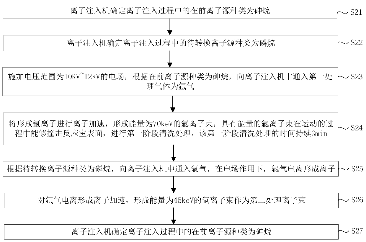
[0065] This embodiment provides a cleaning method for an ion implanter, referring to image 3 , taking the former ion source as arsine and the ion source to be converted as phosphine as an example.

[0066] S21: the ion implanter determines that the type of the previous ion source in the ion implantation process is arsine (AsH3);

[0067] S22: The ion implanter determines that the type of ion source to be converted during the ion implantation process is phosphine (PH3);

[0068] S23: Apply an electric field with a voltage range of 10KV to 12KV. According to the type of the previous ion source is arsine, the first processing gas is introduced into the ion implanter as argon gas. Since argon gas is an inert gas, it is not easy to interact with other objects. reaction, so that argon gas can be used to ionize argon ions under the action of an electric field;

[0069] S24: Accelerate the formed argon ions to form an argon ion beam with an energy of 70keV. The argon ion beam with ...

Embodiment 3

[0075] This embodiment provides a cleaning method for an ion implanter, referring to Figure 4 , taking the previous ion source as arsine and the ion source to be converted as germanium tetrafluoride as an example.

[0076] S31: the ion implanter determines that the type of the previous ion source in the ion implantation process is arsine (AsH3);

[0077] S32: The ion implanter determines that the type of ion source to be converted during the ion implantation process is germanium tetrafluoride (GeF4);

[0078] S33: Apply an electric field with a voltage range of 10KV to 12KV. According to the type of the previous ion source is arsine, and the first processing gas is argon into the ion implanter. Since argon is an inert gas, it is not easy to interact with other objects. reaction, so that argon gas can be used to ionize argon ions under the action of an electric field;

[0079] S34: Accelerate the formed argon ions to form an argon ion beam with an energy of 80keV. The argon ...


PUM


Abstract

The invention relates to the technical field of semiconductor processing, and particularly relates to an ion implanter cleaning method in an ion implantation process. The method comprises the steps ofdetermining the preceding ion source type and the to-be-converted ion source type in an ion implantation process; applying an electric field, and introducing a first processing gas into the ion implanter according to the preceding ion source type so as to enable the first processing gas to be ionized to form a first processing ion beam; performing first-stage cleaning processing on a reaction chamber of the ion implanter by the first processing ion beam; introducing a second processing gas into the ion implanter according to the to-be-converted ion source type so as to enable the second processing gas to be ionized to form a second processing ion beam; and enabling the second processing ion beam to irradiate the reaction chamber and a pipeline of the ion implanter, and carrying out second-stage cleaning processing on the reaction chamber and the pipeline of the ion implanter. According to the invention, different cleaning gases are introduced into the ion implanter according to the ion sources types, so that the problem that it is difficult to adapt to the cleaning requirements in various ion implantation processes in related technologies can be solved.

Description

technical field [0001] The invention relates to the technical field of semiconductor processing, in particular to an ion implanter cleaning method in an ion implantation process. Background technique [0002] As an important part of the semiconductor manufacturing process, the implantation process, especially in the pre-integration stage, involves a lot of ion implantation steps, so the efficiency of ion implantation is of great significance to the production capacity of semiconductor manufacturing plants. [0003] After the machine completes an ion implantation, there will be deposits attached to the reaction chamber and pipeline of the ion source. If it is not removed in time, the attached deposits will be heated and volatilized during the next ion implantation, contaminating the next implantation process. ion. Therefore, in the related art, before switching the gas source, an argon ion beam is usually used to bombard the inner wall of the ion source reaction chamber to r...

Claims


Application Information

Patent Timeline
Patent Type & Authority Applications(China)
IPC IPC(8): H01J37/317
CPCH01J37/3171
Inventor 曹志伟郑刚马富林
Owner HUA HONG SEMICON WUXI LTD
Why Eureka
Try Eureka