Cable joint peeling device for electric power

A cable joint and power technology, applied in the field of power, can solve the problems of slow insulation speed, uncontrollable cutting depth, affecting the efficiency of power construction work, etc., and achieves the effect of strong function, simple structure and good applicability

Active Publication Date: 2020-04-28
国网山东省电力公司临邑县供电公司
View PDF3 Cites 1 Cited by
  • Summary
  • Abstract
  • Description
  • Claims
  • Application Information

AI Technical Summary

Problems solved by technology

[0003] As far as the present is concerned, the current cable breaking method is mainly to use a curved cable knife or a utility knife. The blade cuts into the sheath of the cable, and then peels off the sheath of the cable. Simply cut the insulation on one side of the cable, and then the staff will peel off the insulation from the position where the insulation is cut. This method of peeling off the insulation is slow and cannot control the depth of the cut, which will affect the work of electrical construction. efficiency

Method used


Image

  • Cable joint peeling device for electric power
  • Cable joint peeling device for electric power
  • Cable joint peeling device for electric power

Examples


Embodiment 1

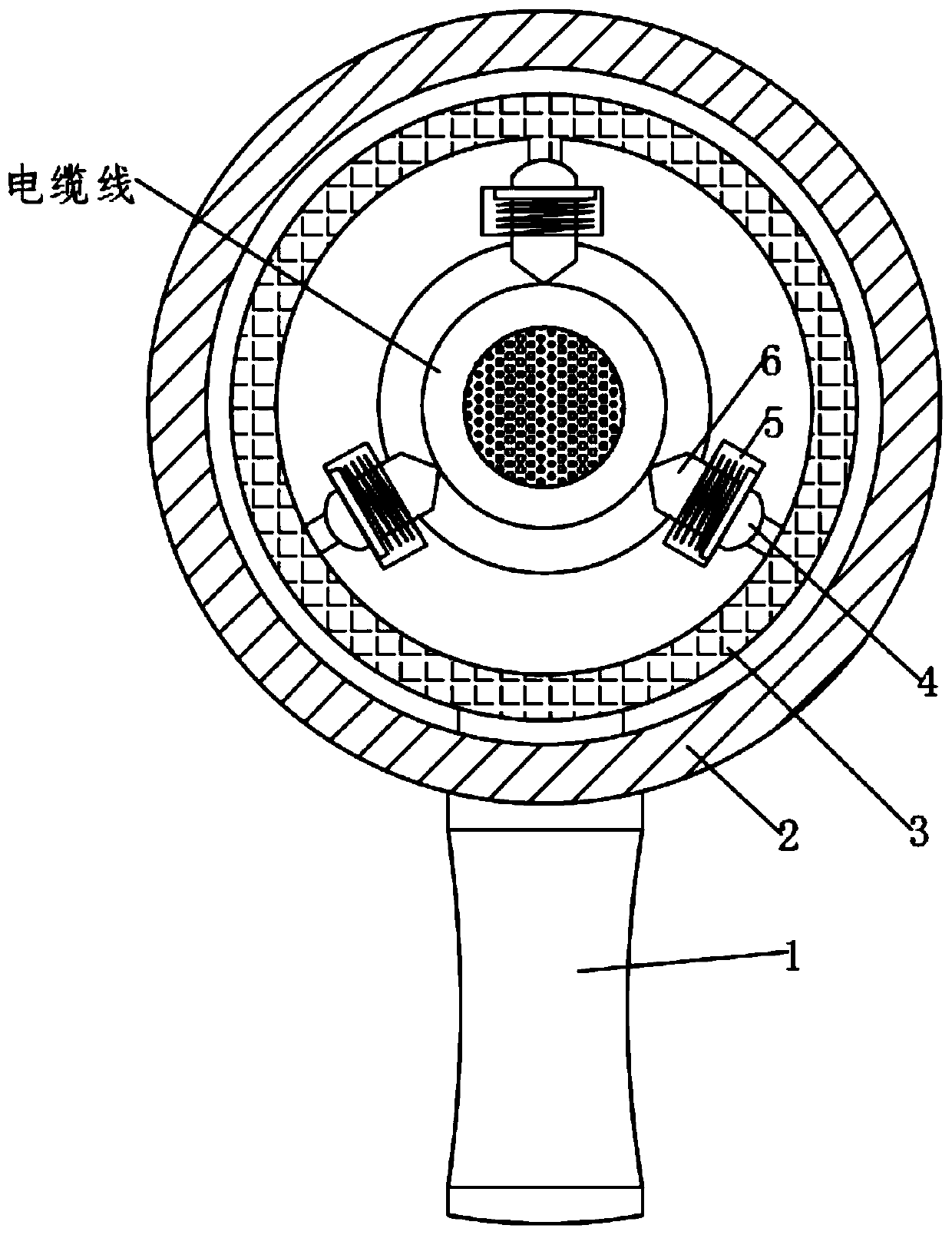
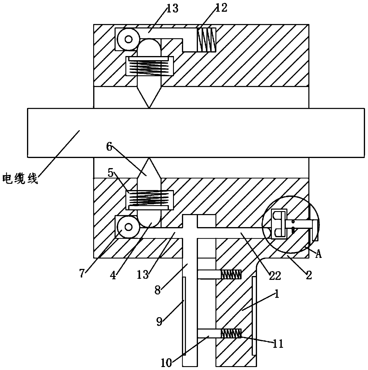
[0022] see Figure 1-4 , a cable joint peeling device for electric power, including a fixed handle 1, a box body 2, a cutter head 6 and a movable handle 8; wherein the fixed handle 1 is fixedly installed on the box body 2, and the movable handle 8 Slidingly installed on the box body 2, a ring rod 3 is slidably installed in the box body 2, and the movable handle 8 is fixedly connected with the ring rod 3, and further drives the movable handle 8 when the movable handle 8 is moved. The circular rod 3 described above moves, the cutter head 6 is slidably installed in the box body 2 through the cutter bar 4, the box body 2 is provided with a chute 5, and the cutter bar 4 is slidably arranged in the chute 5 Inside; said annular bar 3 is fixedly equipped with connecting rod 13, and the end of said connecting rod 13 is rotated and installed with roller 7; The end touches, and then when the movable handle 8 is pressed, the roller 7 is further driven to move, and the roller 7 squeezes t...

Embodiment 2

[0031] In order to further improve the use effect of the device, this embodiment has made the following improvements on the basis of the first embodiment. The improvement is that the fixed handle 1 and the movable handle 8 are equipped with rubber pads 9, and the The rubber pad 9 improves the grip feeling of the device when it is used externally while effectively realizing insulation.

[0032] The working principle of this embodiment: by arranging the rubber pad 9 on the fixed handle 1 and the movable handle 8, the insulation is effectively realized and the grip feeling of the device is improved when the device is used externally.


PUM


Abstract

The invention discloses a cable joint peeling device for electric power. The cable joint peeling device comprises a fixed handle, a box body, a tool bit and a movable handle, wherein the fixed handleis fixedly installed on the box body, the movable handle is installed on the box body in a sliding mode, an annular rod is installed in the box body in a sliding mode, the movable handle is fixedly connected with the annular rod, the tool bit is installed in the box body in a sliding mode through a cutter rod, a sliding groove is formed in the box body, and the cutter rod is arranged in the sliding groove in a sliding mode. A connecting rod is fixedly mounted on the annular rod, and a roller is rotatably mounted at the tail end of the connecting rod; the tail end of the cutter rod is arrangedto be round, the roller makes contact with the tail end of the cutter rod, and a depth control mechanism is arranged on the box body. The device is simple in structure and strong in function; the cutting depth of the cable can be effectively controlled, so that the cable cutting device can be used for different cables; good applicability is realized.

Description

technical field [0001] The invention relates to the field of electric power, in particular to a peeling device for electric cable joints. Background technique [0002] In the technical field of electric power, it is usually necessary to strip the cables and then use the cable cores for connection. [0003] As far as the present is concerned, the current cable breaking method is mainly to use a curved cable knife or a utility knife. The blade cuts into the sheath of the cable, and then peels off the sheath of the cable. Simply cut the insulation on one side of the cable, and then the staff will peel off the insulation from the position where the insulation is cut. This method of peeling off the insulation is slow and cannot control the depth of the cut, which will affect the work of electrical construction. efficiency. Contents of the invention [0004] The object of the present invention is to provide a peeling device for electrical cable joints, so as to solve the probl...

Claims


Application Information

Patent Timeline
Patent Type & Authority Applications(China)
IPC IPC(8): H02G1/12H01R43/28
CPCH01R43/28H02G1/1224H02G1/1236
Inventor 梁锐根
Owner 国网山东省电力公司临邑县供电公司
Why Eureka
Try Eureka