laser cutting machine

A cutting machine and laser technology, applied in the direction of welding/cutting auxiliary equipment, auxiliary devices, laser welding equipment, etc., can solve the problems of easy damage to internal wires, low production efficiency, and partial stripping of waste materials, so as to avoid damage to the inside of wires and production The effect of high efficiency and reduced defective rate

Inactive Publication Date: 2016-02-03
DONGGUAN SANXIN PRECISION MACHINERY
View PDF8 Cites 0 Cited by
  • Summary
  • Abstract
  • Description
  • Claims
  • Application Information

AI Technical Summary

Problems solved by technology

[0003] The traditional laser machine that cuts the outer layer of aluminum foil of the wire will easily damage the inner wire when cutting too deep, and it is difficult to peel off the waste part when cutting too shallow; and peeling off the waste part requires manual processing, which has high labor costs and high production efficiency. Low, and easy to damage the wire, high defective rate

Method used


Image

  • laser cutting machine
  • laser cutting machine
  • laser cutting machine

Examples


Embodiment Construction

[0021] In order to further understand the features, technical means, and specific objectives and functions achieved by the present invention, the present invention will be further described in detail below in conjunction with the accompanying drawings and specific embodiments.

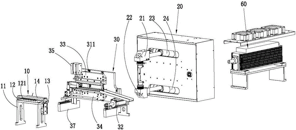
[0022] see figure 1 , the present invention discloses a laser cutting machine, which includes a stage 10 for placing wires, an X-axis cutting device 20 , a bending and shifting device 30 and a laser 60 . The X-axis cutting device 20 has an upper laser head 21 and a lower laser head 22 , and the laser light emitted by the laser 60 is transmitted to the upper laser head 21 and the lower laser head 22 through the optical path mechanism.

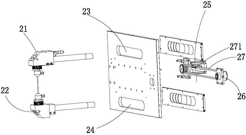
[0023] Please also refer to figure 2 , the X-axis cutting device 20 is provided with a first chute 23 and a second chute 24 , and the first chute 23 is parallel to the second chute 24 . The upper laser head 21 is set to slide on the first chute 23 and is located above...


PUM


Abstract

A laser cutting machine comprises an X-axis cutting device and a bending and moving device, wherein the X-axis cutting device is provided with an upper laser head and a lower laser head, a first slide groove and a second slide groove are formed in the X-axis cutting device, the first slide groove is parallel to the second slide groove, the upper laser head is arranged on the first slide groove in a sliding mode and located above a platform, and the lower laser head is arranged on the second slide groove in a sliding mode and located below the platform. The bending and moving device comprises a base and a moving air cylinder used for controlling the base to move forward and backward, wherein an upper clamping portion, a lower clamping portion, two longitudinally-parallel first guide rails, an upper bending air cylinder and a lower bending air cylinder are arranged on the base, the upper clamping portion and the lower clamping portion are transversely erected on the two first guide rails respectively, and the upper clamping portion and the lower clamping portion are connected with the bending air cylinders respectively. The upper laser head and the lower laser head are matched with each other to cut the upper face of a wire rod and the lower face of the wire rod respectively, and therefore the cutting depth is effectively controlled, the inner portion of the wire rod is prevented from damage, manual operation is replaced, production efficiency is high, labor cost is saved, and the defective rate is lowered.

Description

technical field [0001] The invention relates to a cutting machine, in particular to a laser cutting machine which can automatically cut the outer layer of aluminum foil of a wire and has a low defective rate. Background technique [0002] With the advancement of science and technology, some electronic industries at this stage, such as integrated circuit boards, often need to be connected with upper cables. However, when soldering the cable, sometimes the aluminum foil on the outer layer of the cable needs to be removed. [0003] The traditional laser machine that cuts the outer layer of aluminum foil of the wire will easily damage the inner wire when cutting too deep, and it is difficult to peel off the waste part when cutting too shallow; and peeling off the waste part requires manual processing, which has high labor costs and high production efficiency. Low, and easy to damage the wire, high defective rate. Contents of the invention [0004] Based on this, it is necess...

Claims


Application Information

Patent Timeline
Patent Type & Authority Patents(China)
IPC IPC(8): B23K26/38B23K26/70
CPCB23K26/0869B23K26/38B23K26/702B23K37/0435
Inventor 姚天金
Owner DONGGUAN SANXIN PRECISION MACHINERY
Why Eureka
Try Eureka