
A manufacturing process of explosive composite pipe with negative pressure cavity based on liquid explosive

A technology for liquid explosives and manufacturing processes, applied in manufacturing tools, metal processing equipment, welding equipment, etc., can solve the problems of increased explosive welding cost, inability to completely eliminate bases, low bonding strength, etc., and achieve simple charging and high bonding rate. , The effect of good welding quality

Active Publication Date: 2021-08-03
ANHUI UNIVERSITY OF ARCHITECTURE
View PDF5 Cites 0 Cited by
  • Summary
  • Abstract
  • Description
  • Claims
  • Application Information

AI Technical Summary

Problems solved by technology

Small-diameter composite pipes need to be obtained through continuous drawing of medium and large-diameter composite pipes, and the drawing process often causes metal peeling and delamination
Explosive welding directly using small-diameter metal round pipes has problems such as difficulty in charging and uneven charging
In addition, in order to obtain a composite pipe with higher bonding strength, it is usually necessary to impose strong constraints on the outside of the base pipe, usually steel molds and serious wear and tear, which greatly increases the cost of explosive welding
The traditional explosive welding process of metal circular tubes cannot completely remove the air between the base and the cladding tube, which makes the composite tube bulge, resulting in problems such as low bonding rate and low bonding strength.

Method used


Image

  • A manufacturing process of explosive composite pipe with negative pressure cavity based on liquid explosive
  • A manufacturing process of explosive composite pipe with negative pressure cavity based on liquid explosive
  • A manufacturing process of explosive composite pipe with negative pressure cavity based on liquid explosive

Examples


Embodiment Construction

[0033] The technical solutions in the embodiments of the present invention will be clearly and completely described below in conjunction with the embodiments of the present invention. Apparently, the described embodiments are only some of the embodiments of the present invention, not all of them. Based on the embodiments of the present invention, all other embodiments obtained by persons of ordinary skill in the art without making creative efforts belong to the protection scope of the present invention.

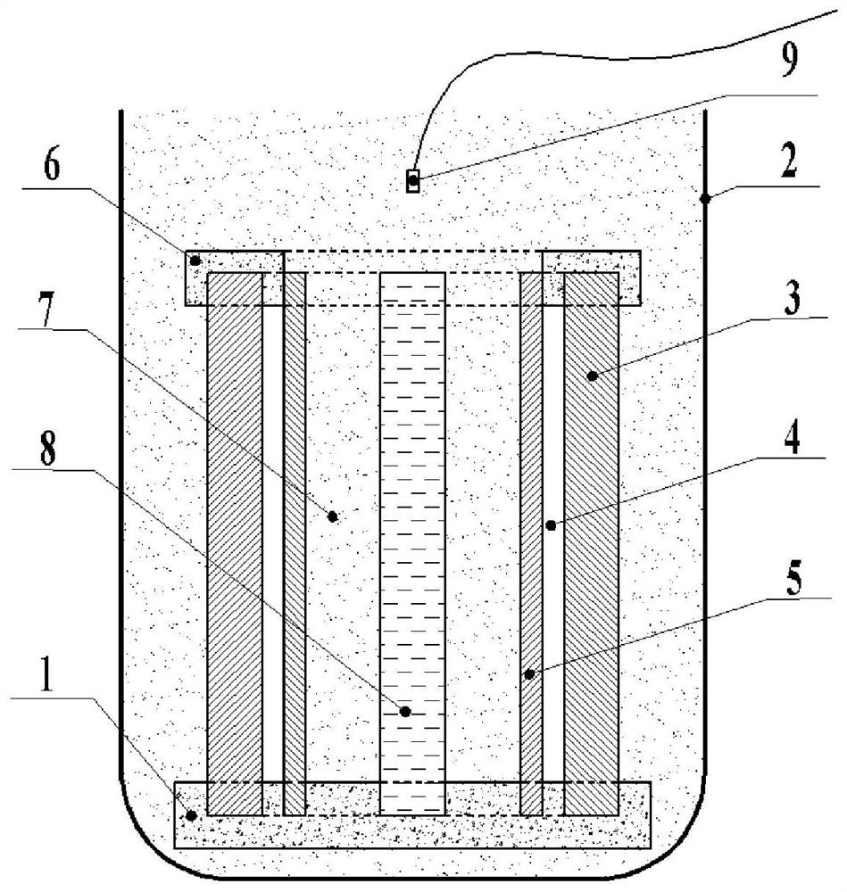
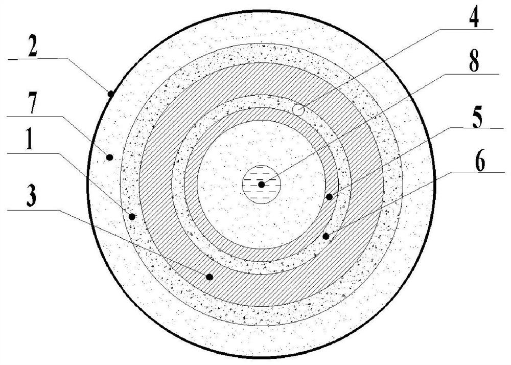
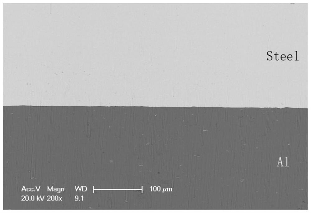
[0034] Refer to attached Figure 1-3 Describe the manufacturing process of the explosive composite pipe with a negative pressure cavity based on liquid explosives according to the embodiment of the present invention. The manufacturing process of the explosive composite pipe includes the following steps:

[0035] S1. Prepare the metal round pipe and soft base that need to be explosively welded. The metal round pipe includes at least the cladding pipe and the base pipe, wherein...


PUM

PropertyMeasurementUnit
thicknessaaaaaaaaaa
thicknessaaaaaaaaaa
densityaaaaaaaaaa

Abstract

The invention provides a liquid explosive-based explosive composite pipe manufacturing process with a negative pressure cavity, which includes: coaxially installing the cladding pipe and the base pipe on the soft base from the inside to the outside, and according to the Calculate the amount of explosives according to the specifications, and install the inner tube to adjust the water column, use the sealing ring to seal the upper end of the annular cylindrical gap between the covering pipe and the base pipe, and use a vacuum pump to pump the annular cylindrical cavity into a negative pressure and seal it , place the assembled tube blank coaxially with the container and inject liquid explosives, and detonate the explosives to obtain metal composite tubes. The invention can greatly improve the production efficiency; the charge is uniform, the combination rate of the composite pipe is high, the welding quality is good, no constraint mold is required during the welding process, the production cost can be greatly reduced, and the circular cylindrical cavity is pumped into a vacuum pump. Negative pressure greatly reduces the influence of air on explosive welding, which not only improves the bonding quality of composite pipes, but also reduces the amount of explosives used.

Description

technical field [0001] The invention belongs to the field of explosive welding, and relates to a manufacturing process of an explosive composite pipe with a negative pressure cavity based on liquid explosives. Background technique [0002] Explosive welding technology is a welding method that uses the energy generated by the instantaneous explosion of explosives to make the cladding material collide with the base material at high speed, thereby achieving a metallurgical bond between the metal surfaces to be welded. It is usually used for welding between metal materials with large differences in physical and chemical properties. Metal explosive composite pipes are widely used in petroleum, chemical, aerospace and other fields. Existing explosive clad pipes are mainly formed by coiling and welding explosive clad plates. However, for some small-diameter composite pipes, it is difficult for welding equipment to achieve internal and external layered welding, and the formed comp...

Claims


Application Information

Patent Timeline
Patent Type & Authority Patents(China)
IPC IPC(8): B23K20/08
CPCB23K20/085
Inventor 余勇刘菲张竣瑜李凯赵俊徐沛保
Owner ANHUI UNIVERSITY OF ARCHITECTURE
Learn More