Exhaust device, exhaust control method and mold structure with exhaust device

An exhaust device and mold technology, applied in the coating and other directions, can solve the problems of low gas reserves, bursting, air trapping in plastic products, etc., and achieve the effect of avoiding trapped air and timely and rapid exhausting.

Inactive Publication Date: 2020-05-01
HESHAN LESSO IND DEV
View PDF10 Cites 3 Cited by
  • Summary
  • Abstract
  • Description
  • Claims
  • Application Information

AI Technical Summary

Problems solved by technology

[0002] During the injection molding process, the plastic raw material needs to flow into the cavity through the flow channel, and the gas in the cavity is often exhausted by using parting surfaces, thimbles, insert pins, exhaust steel, inserts, etc. However, this method is only suitable for Injection mold with small cavity inner wall space and less gas storage in the cavity; when the wall thickness of the injection molded product is thicker, the injection mold cavity space is large, the gas storage in the cavity is large, and the entire mold cavity is currently closed state, this exhaust method cannot achieve the effect of rapid exhaust, resulting in problems such as air trapping, scorching, and insufficient welding of plastic products. It is easy to burst during performance testing, which seriously affects the surface appearance and molding quality of plastic products. and molding pass rate

Method used


Image

  • Exhaust device, exhaust control method and mold structure with exhaust device
  • Exhaust device, exhaust control method and mold structure with exhaust device
  • Exhaust device, exhaust control method and mold structure with exhaust device

Examples


Embodiment 1

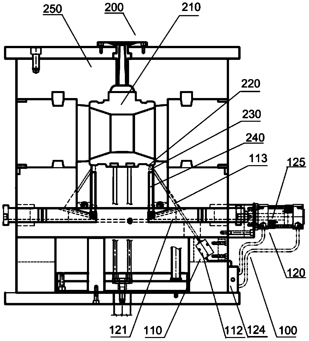
[0032] Such as Figure 1 to Figure 3 Shown is an embodiment of the exhaust device 100 of the present invention, the exhaust device 100 of this embodiment is applied to a mold structure 200; the mold structure 200 is provided with a cavity 210 that can communicate with the external environment, and the bottom of the cavity 210 A temperature-sensing point 220 is provided; the exhaust device 100 includes a controller, a temperature-sensing mechanism 110 connected to the input end of the controller, and a mechanical slider mechanism 120 connected to the output end of the controller, and the temperature-sensing mechanism 110 is signal-connected to the temperature-sensing point 220; The mold structure 200 is provided with a guide hole 230 communicated with the cavity 210 , and the guide hole 230 is provided with a sealing insert 240 that can be raised by the mechanical slider mechanism 120 to close the cavity 210 .

[0033]During the implementation of this embodiment, the high-tempe...

Embodiment 2

[0037] This embodiment is an embodiment of the exhaust gas control method of the exhaust device 100 in the first embodiment, including the following steps:

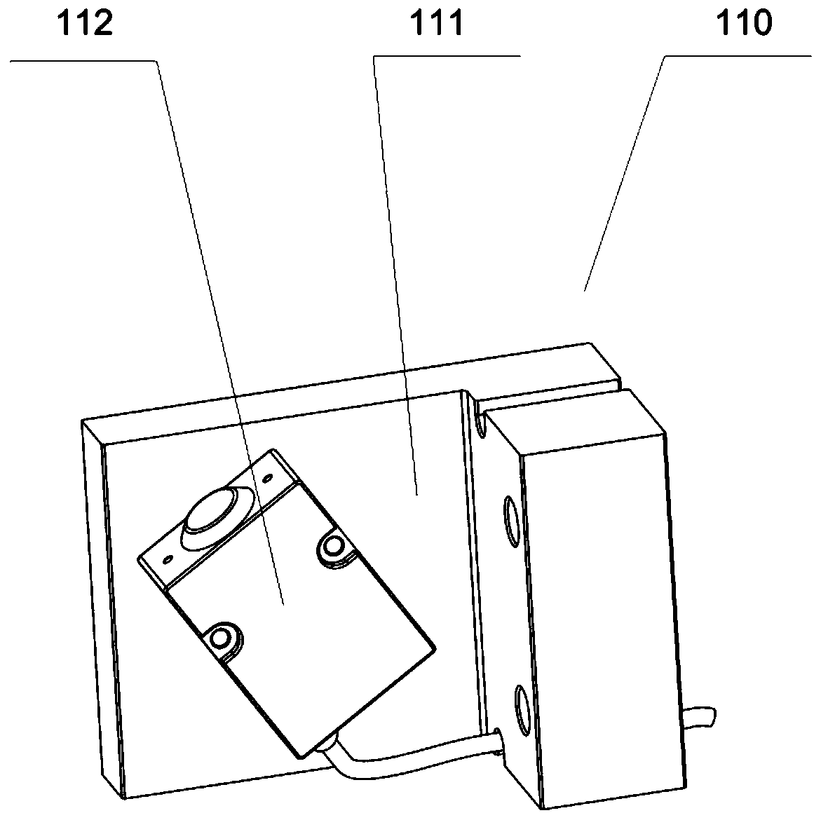
[0038] When the high-temperature fluid plastic flows to the temperature sensing point 220 in the cavity 210, the infrared temperature sensor 112 transmits the received signal to the controller, and the controller controls the solenoid valve 124 to open, connecting the air source and the cylinder 125;

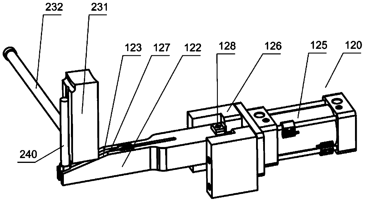
[0039] The air cylinder 125 pushes the slider 122 to move under the air pressure, and the end of the sealing insert 240 slides in the T-shaped groove 127 and moves upward along the slope 123 to close the cavity 210 .

[0040] Through the above steps, the gas in the cavity 210 can be effectively and quickly removed, and the cavity 210 can be closed in time to ensure the smooth molding of the plastic product.

Embodiment 3

[0042] Such as Figure 4 to Figure 5 Shown is an embodiment in which the exhaust structure of Embodiment 1 is applied to a mold structure 200. The mold structure 200 includes a mold frame 250, a cavity 210, a glue injection system 260 communicating with the cavity 210, a core pulling system 270, and a thimble system 280 As well as the previous exhaust device 100 , the temperature sensing mechanism 110 , the mechanical slider mechanism 120 , the glue injection system 260 , the core pulling system 270 , and the thimble system 280 are all installed on the mold frame 250 .

[0043] During the implementation of this embodiment, the high-temperature molten high-temperature fluid plastic is injected into the cavity 210 through the injection system 260. When the high-temperature fluid plastic touches the temperature-sensing mechanism 110, the mechanical slider mechanism 120 is controlled to drive the sealing insert 240 Rising and closing the cavity 210, the high-temperature fluid plas...


PUM


Abstract

The invention relates to the technical field of plastic molding, in particular to an exhaust device, an exhaust control method and a mold structure with the exhaust device. The exhaust device is applied to the mold structure, wherein a cavity capable of communicating with the external environment is arranged in the mold structure, and a temperature sensing point is arranged at the bottom of the cavity; the exhaust device comprises a controller, a temperature sensing mechanism connected to the input end of the controller and a mechanical sliding block mechanism connected to the output end of the controller, and the temperature sensing mechanism is in signal connection with the temperature sensing point; and a guide hole communicating with the cavity is arranged in the mold structure, and asealing insert needle capable of rising by the action of the mechanical sliding block mechanism to seal the cavity is arranged in the guide hole. According to the exhaust device, the exhaust control method and the mold structure with the exhaust device, the open type cavity is adopted to inject plastic products firstly, so that the air exhaust is quickly carried out in time, and the defective phenomena of gas entrapment, charring, insufficient welding, bursting in performance test and the like of the plastic products are effectively avoided; and when high-temperature fluid plastic flows to thetemperature sensing point, the mechanical sliding block mechanism is triggered to drive the sealing insert needle to rise to seal the cavity, so that it is ensured that the injection molding processof the plastic products is smoothly completed.

Description

technical field [0001] The invention relates to the technical field of plastic molding, and more specifically, to an exhaust device, an exhaust control method and a mold structure thereof. Background technique [0002] During the injection molding process, the plastic raw material needs to flow into the cavity through the flow channel, and the gas in the cavity is often exhausted by using parting surfaces, thimbles, insert pins, exhaust steel, inserts, etc. However, this method is only suitable for Injection mold with small cavity inner wall space and less gas storage in the cavity; when the wall thickness of the injection molded product is thicker, the injection mold cavity space is large, the gas storage in the cavity is large, and the entire mold cavity is currently closed state, this exhaust method cannot achieve the effect of rapid exhaust, resulting in problems such as air trapping, scorching, and insufficient welding of plastic products. It is easy to burst during per...

Claims


Application Information

Patent Timeline
Patent Type & Authority Applications(China)
IPC IPC(8): B29C45/33B29C45/34B29C45/00B29C45/76
CPCB29C45/0025B29C45/33B29C45/34B29C45/76B29C2945/76735
Inventor 谭洪潘耀华谭建志郭伟
Owner HESHAN LESSO IND DEV
Why Eureka
Try Eureka