Brake airplane wheel cooled by utilizing airplane landing kinetic energy and brake heat

A technology of brakes and kinetic energy, applied in the direction of aircraft brake arrangement, wheel type, brake, etc., can solve problems such as damage, puncture, air leakage, etc., and achieve the effect of reducing the temperature of the wheel, shortening the time interval, and improving the cooling efficiency

Pending Publication Date: 2020-05-01
长沙鑫航机轮刹车有限公司
View PDF0 Cites 3 Cited by
  • Summary
  • Abstract
  • Description
  • Claims
  • Application Information

AI Technical Summary

Problems solved by technology

[0003] However, often when designing an aircraft, based on overall considerations such as size and weight reduction requirements, the size and weight of the brake disc should not have too much performance margin under the premise of meeting the performance requirements, resulting in the brake disc under normal braking conditions. The temperature reaches 400℃~500℃, and the wheel reaches above 100℃
Considering the situation of aborted takeoff, short landing time and high energy during continuous takeoff, the heat from the previous brake wheel and brake disc cannot be completely dissipated, the two brake energy superimposed, and the temperature at the tire foot is too high. If the temperature is high (GJB 1184A-2005 general specification for aircraft wheels and brakes stipulates that the temperature at the tire foot should be less than 177°C), there will be a risk of tire blowout or air leakage, as well as the risk of damage to other parts due to high temperature, resulting in the failure of the aircraft. consecutive take-offs in a short period of time

Method used


Image

  • Brake airplane wheel cooled by utilizing airplane landing kinetic energy and brake heat
  • Brake airplane wheel cooled by utilizing airplane landing kinetic energy and brake heat
  • Brake airplane wheel cooled by utilizing airplane landing kinetic energy and brake heat

Examples


Embodiment 1

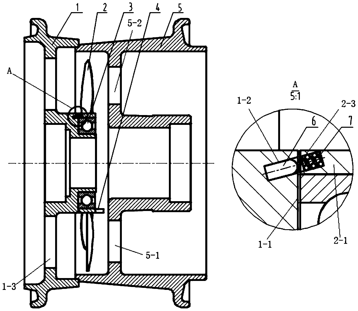
[0025] see Figure 1 to Figure 6 In this embodiment, a brake wheel that uses aircraft landing kinetic energy and braking heat to cool down includes an outer half hub 1, an unpowered fan 2, a bearing 3, an inner half hub 5 and a linkage structure.

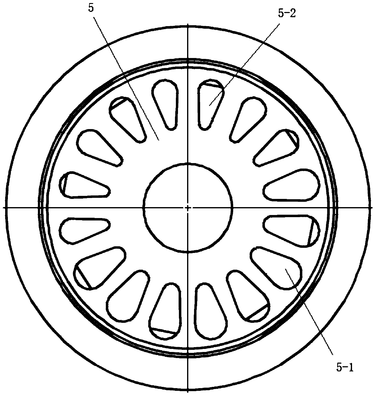
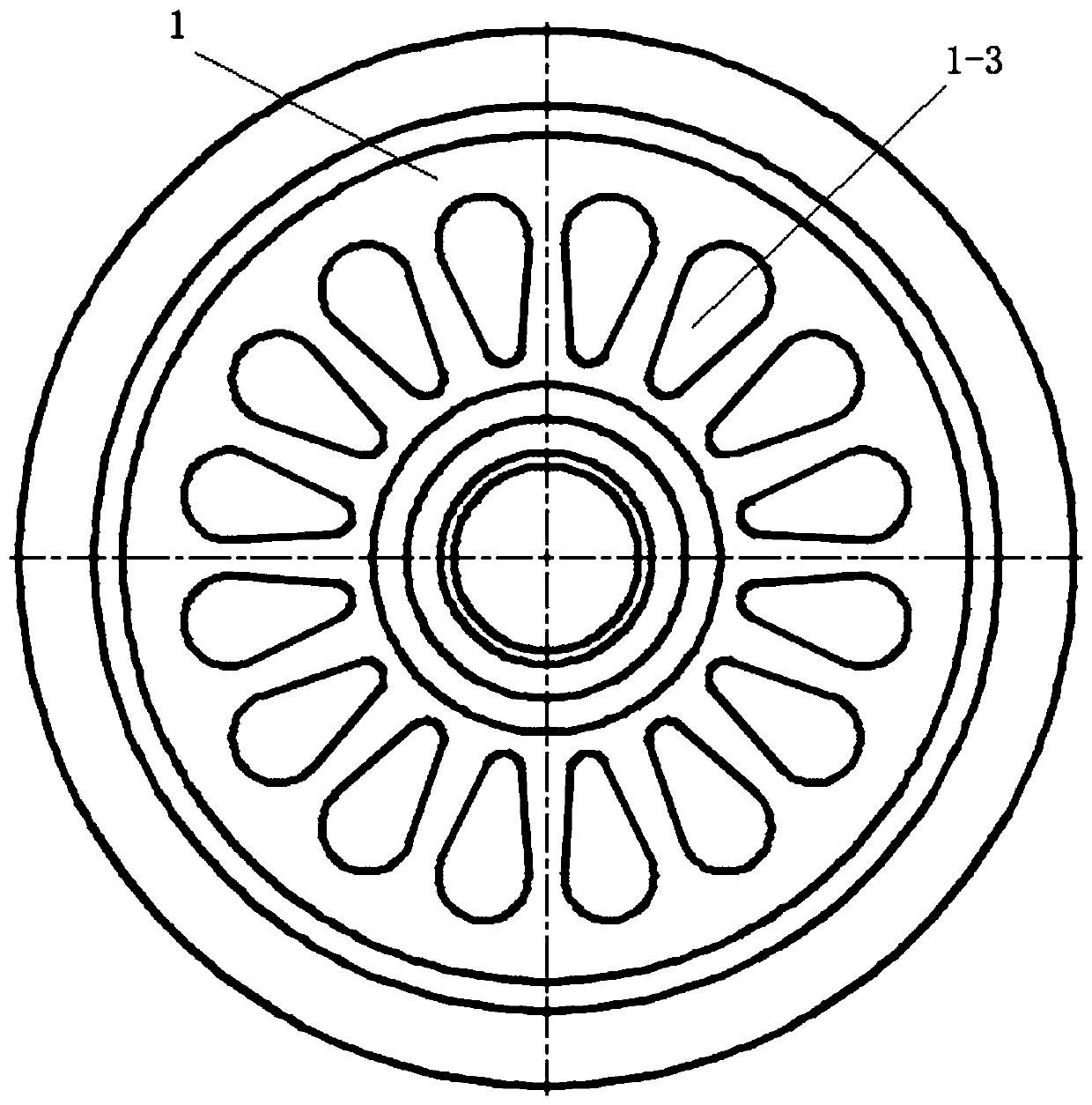
[0026] The outer half hub 1 and the inner half hub 5 are arranged coaxially, and are fixed by bolts to form a complete hub. The middle part of the spokes of the outer half hub 1 protrudes to the right to form a sleeve. The unpowered fan 2 is arranged on the sleeve of the outer half hub 1 through a bearing 3, and the unpowered fan 2 is located between the outer half hub 1 and the inner half hub 5. The linkage structure is arranged on the unpowered fan 2 and the outer half hub 1. The linkage structure links the unpowered fan 2 and the outer half hub 1 when the outer half hub 1 rotates at a high speed, and disconnects the unpowered fan when the rotation speed of the outer half hub 1 decreases. 2 Linkage with outer half wheel hub 1.

[00...


PUM


Abstract

The invention discloses a brake airplane wheel cooled by utilizing airplane landing kinetic energy and brake heat. The brake airplane wheel comprises an outer half wheel hub, an unpowered fan, a bearing, an inner half wheel hub and a linkage structure, wherein the outer half wheel hub and the inner half wheel hub are coaxially arranged and are spliced and fixed into a complete wheel hub, the outerhalf wheel hub and the middle portion project towards the right side to form a shaft sleeve, the unpowered fan is arranged on the shaft sleeve of the outer half wheel hub through a bearing and located between the outer half wheel hub and the inner half wheel hub, the linkage structure is arranged on the unpowered fan and the outer half wheel hub, and is in linkage with the unpowered fan and the outer half wheel hub to rotate synchronously when the rotating speed of the outer half wheel hub is high, and the linkage between the unpowered fan and the outer half wheel hub is disconnected when therotating speed of the outer half wheel hub is reduced. According to the invention, the braking energy of the airplane wheel is rapidly guided into external air, so that the temperature of the airplane wheel and the braking device can be rapidly reduced, the cooling efficiency can be improved, and the continuous take-off time interval of the airplane is shortened.

Description

Technical field [0001] The invention relates to the field of aircraft safety, in particular to a brake wheel that utilizes aircraft landing kinetic energy and braking heat to cool down. Background technique [0002] As the weight of the aircraft increases and the braking energy increases, the time interval between successive takeoffs becomes shorter and shorter. [0003] But often when designing an aircraft, based on overall considerations such as size and weight reduction requirements, the size and weight of the brake discs can not have too much performance margin under the premise of meeting the performance requirements. As a result, under normal braking conditions, the brake discs The temperature reaches 400℃~500℃, and the wheel reaches above 100℃. Considering the possible suspension of takeoff, short re-landing time and high energy during continuous take-off, the heat suffered by the previous brake wheel and brake disc cannot be completely dissipated, the two braking energy is...

Claims


Application Information

Patent Timeline
Patent Type & Authority Applications(China)
IPC IPC(8): B64C25/42B60T5/00B64C25/36
CPCB60T5/00B64C25/36B64C25/42
Inventor 肖卿张海
Owner 长沙鑫航机轮刹车有限公司
Why Eureka
Try Eureka