
Lubricating structure of drive axle differential mechanism and drive axle differential mechanism assembly

A lubricating structure and differential technology, applied in the direction of differential transmission, gear lubrication/cooling, transmission, etc., can solve the problem of reducing the service life of the differential assembly and drive axle, internal heat cannot be discharged, and parts are abnormal Wear and other problems, to achieve the effect of lowering temperature, improving life and reducing impurities

Pending Publication Date: 2020-05-01
SHAANXI HANDE AXLE CO LTD
View PDF0 Cites 3 Cited by
  • Summary
  • Abstract
  • Description
  • Claims
  • Application Information

AI Technical Summary

Problems solved by technology

Poor lubrication prevents lubricating oil from fully entering the mutual contact surfaces of the parts, resulting in abnormal wear of parts and internal heating of the differential shell. At the same time, poor lubrication also prevents the internal heat from being effectively discharged from the differential shell.
These problems greatly reduce the service life of the differential assembly and drive axle

Method used


Image

  • Lubricating structure of drive axle differential mechanism and drive axle differential mechanism assembly
  • Lubricating structure of drive axle differential mechanism and drive axle differential mechanism assembly
  • Lubricating structure of drive axle differential mechanism and drive axle differential mechanism assembly

Examples


Embodiment

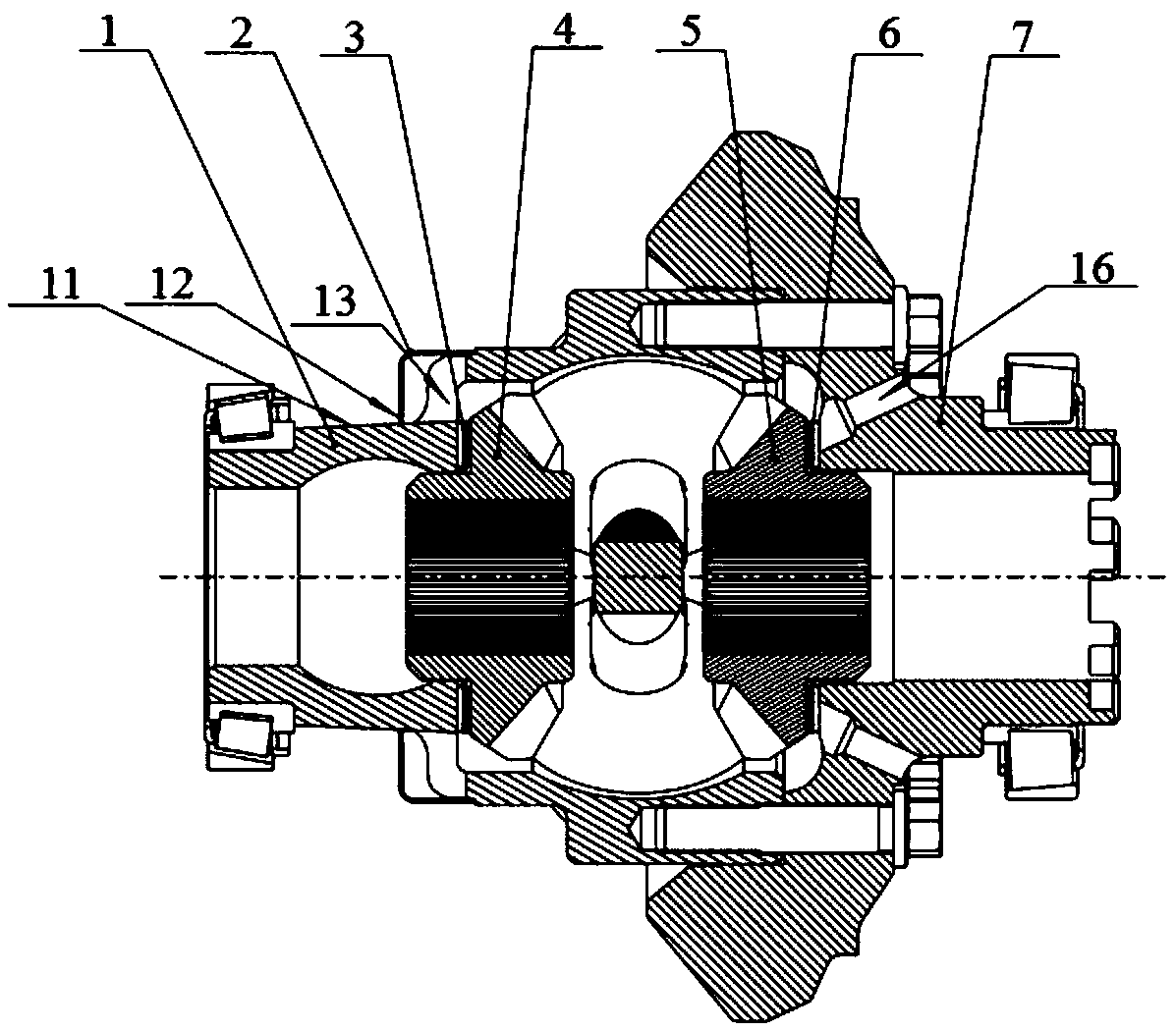
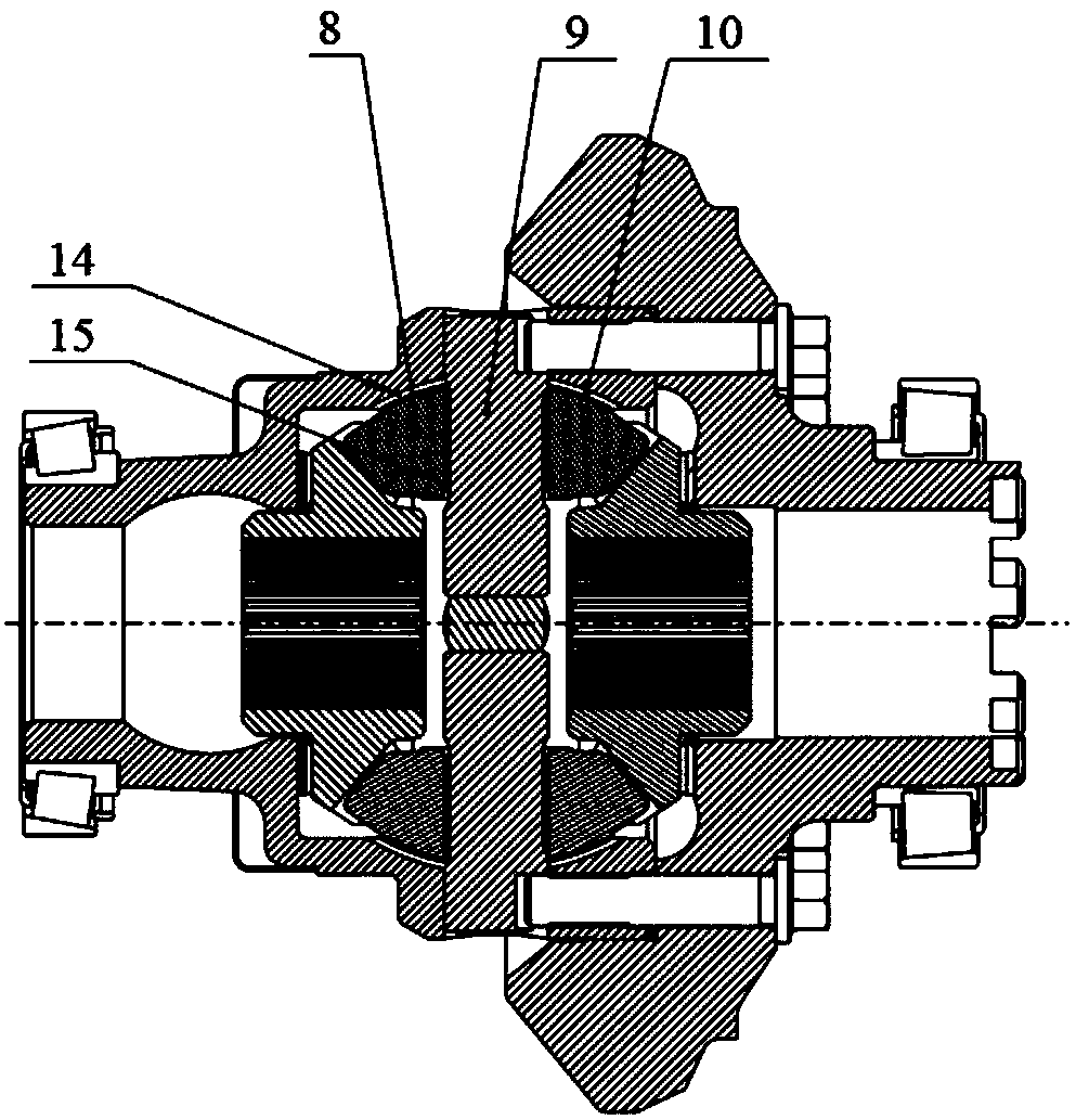
[0045] Such as figure 1 , 2 As shown, the transaxle differential adopting the new lubrication method in this embodiment includes a tooth side differential case 1, an oil deflector cover 2, a left side gear spacer 3, a left side gear 4, and a right side gear 5 , Right side shaft gear spacer 6, tooth back side differential case 7, planetary wheel 8, cross shaft 9, planetary wheel spacer 10. Its features and functions are as follows:

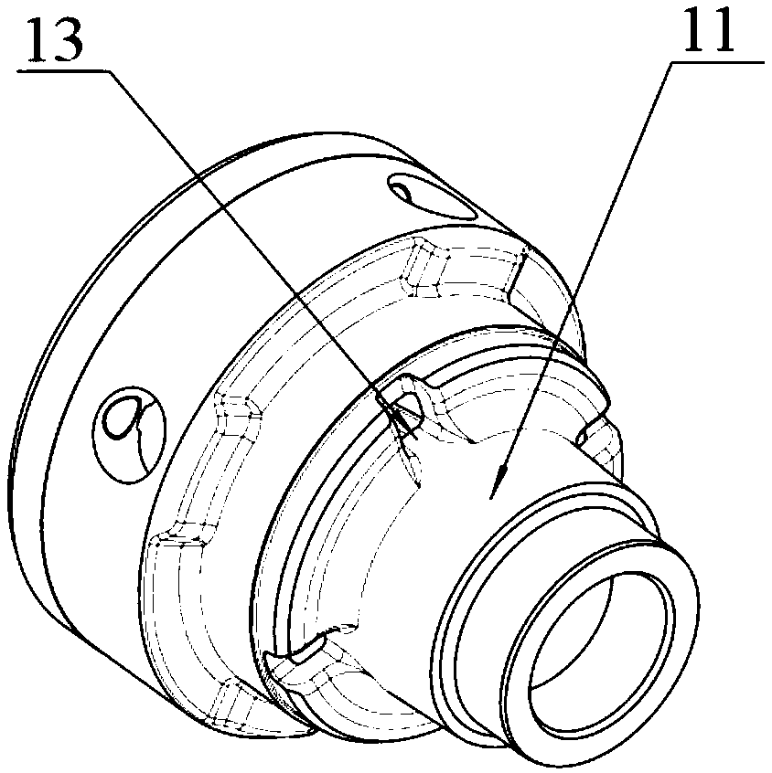
[0046] The outer cone surface 11 of the gear side differential case 1 is a rotary conical surface with a certain draft angle. The oil adhering to the conical surface enters the differential cavity through the oil inlet 12 of the oil retaining cover and the oil inlet 13 of the differential housing on the tooth side under the action of centrifugal force. There is a certain gap between the oil retaining cover 2 assembled on the tooth surface side differential case 1 and the conical surface of the differential case to form the oil retaining cover oi...


PUM


Abstract

The invention relates to a lubricating structure of a drive axle differential mechanism and a drive axle differential mechanism assembly. The lubricating structure comprises an oil baffle cover, the oil baffle cover is fixedly arranged on the circumferential outer side of a tooth surface side differential mechanism shell of the differential mechanism, an outer conical surface is arranged at the axial joint between the tooth surface side differential mechanism shell and a half axle of the differential mechanism, the rotation diameter of the end, facing the half axle, of the outer conical surface is increased, a gap is formed between the oil baffle cover and the outer conical surface, so that lubricating oil flows inwards, and an oil inlet leading to an inner cavity is formed in the inner side, at the gap, of the tooth surface side differential mechanism shell. According to the lubricating structure of the drive axle differential mechanism and the drive axle differential mechanism assembly, the oil can be promoted to be fed and discharged, oil circulation of oil in the inner cavity of the differential mechanism shell and oil outside the differential mechanism shell is achieved through feeding and discharging of the oil, impurities and heat generated inside the differential mechanism can be brought out, the impurities in the inner cavity of the differential mechanism shell are reduced, the inner temperature of the differential mechanism is reduced, meanwhile, oil microcirculation is formed in the inner cavity, and the lubricating effect is improved, and therefore, internal abrasion of the differential mechanism can be remarkably reduced, and service lives of the differential mechanism and the whole axle are greatly prolonged.

Description

technical field [0001] The invention relates to the technical field of an automobile drive axle differential assembly, in particular to a lubrication structure of a drive axle differential and a drive axle differential assembly. Background technique [0002] In the existing heavy-duty vehicle drive axle system, the types with a high failure rate of the inter-wheel differential assembly include abnormal wear of the differential housing, abnormal wear of the cross shaft, fracture of the cross shaft, burning of the planetary wheel and the cross shaft, etc. After analyzing the cause of this type of failure, it is mainly due to the poor internal lubrication of the inter-wheel differential. Poor lubrication prevents lubricating oil from fully entering the mutual contact surfaces of the parts, resulting in abnormal wear of parts and internal heating of the differential shell. At the same time, poor lubrication also prevents internal heat from being effectively discharged from the d...

Claims


Application Information

Patent Timeline
Patent Type & Authority Applications(China)
IPC IPC(8): F16H57/04F16H48/38F16H48/08
CPCF16H57/0423F16H57/0424F16H57/0427F16H57/0493F16H57/0482F16H48/38F16H48/08
Inventor 丁炜琦何维聪张龙巩占峰
Owner SHAANXI HANDE AXLE CO LTD
Learn More